Version 13.03.2015
Page
3
1.3.
Setting the dip switches of the CAN-‐box RLC-‐TV521
Vehicle/ navigation
Dip 1 Dip 2 Dip 3 Dip 4 Dip 5 Dip 6
PCM 3 with video-‐in-‐motion activated
ON
ON
OFF
OFF
OFF
OFF
PCM 3 with video-‐in-‐motion deactivated
OFF
ON
OFF
OFF
OFF
OFF
PCM 3.1 with video-‐in-‐motion activated
ON
ON
OFF
OFF
OFF
ON
PCM 3.1 with video-‐in-‐motion deactivated OFF
ON
OFF
OFF
OFF
ON
Note
: Dip switch functions of the CAN-‐box RLC-‐TV-‐521
Dip 1 – activation TV-‐free
Dip 2 – rear-‐view camera existing
Dip 3 – Coding rear-‐view camera by white cable
Dip 4 – Coding ParkAssistant by white cable (only PCM3.1, PCM3 no function)
Dip 5 – no function
Dip 6 – no function / CAN-‐bus termination
1.4.
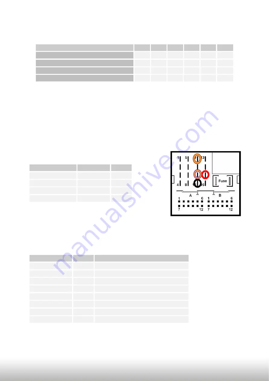
Pin-‐assignments
Pin-‐assignment factory connector
No liability for vehicle wire colors and pin definition!
Possible changes by the vehicle manufacturer. The given
information must be verified by the installer.
Pin-‐assignment of the CAN-‐box RLC-‐TV521 (Molex 8pin)
Cable colour
Pin-‐No. Assignment
●
Yellow
Pin 4
CAN-‐HIGH – connection to the head-‐unit
●
Blue
Pin 3
CAN-‐LOW – connection to the head-‐unit
●
● Yellow/Black Pin 8
CAN-‐HIGH – connection to the vehicle
●
● Blue/Black
Pin 7
CAN-‐LOW – connection to the vehicle
●
Red
Pin 1
+12V permanent
● Black
Pin 5
Ground
●
Green
Pin 2
+12V rear-‐view camera (max. 400mA)
●
White
Pin 6
Alternatively coding
Cable colour
Assignment Pin No.
●
Red
+12V battery Pin 15
● Black
Ground
Pin 12
●
●
Orange/brown CAN-‐low
Pin 9
●
●
Orange/purple CAN-‐high
Pin 11


