background image

8

9

Installation

Installation

NOTE:

 All Séura drawing packages indicate generalized nominal residential wood 

framing construction, and are not indicative of any particular building code. 
It is the installers responsibility that all electrical, audio/visual, and framing 
construction are code compliant to the municipality in which the product is 
being installed. Modifications made to Séura recommendations are at the 
sole discretion of the installer and release Séura of all liability.

Inspect the desired location for installation and be aware of all electrical 

wiring pathways, water pipes, gas lines, or other potentially hazardous 

conditions that may exist to protect from accidental damage during creation 
of on-site conditions. 

Ensure all required electrical specifications are adhered to and have been 

installed by the appropriate individuals and are code approved.

Ensure all framing requirements, if needed have been completed to building code and pose no structural issues.

It is REQUIRED that this product is plugged into an electrical outlet protected by a Ground Fault Circuit Interrupter (GFCI) to protect against electric 

shock, fire, and/or injury. Failure to do so will void any warranty for this product.

Only qualified individuals should attempt to service the product. Removing covers can expose you to high voltage and other dangerous conditions.

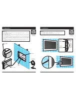
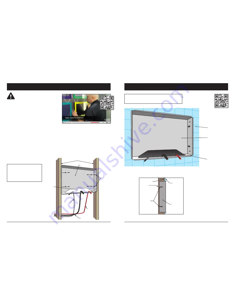
Step 1

Install back box to framing members using the 
provided four screws and washers through 

screw-mounting slots in back box. Ensure that 

the front of the box is flush with finished wall 
and mounting tabs will rest on finished wall 
surface. Feed power and other desired cords 
through pass-through port.

Read all installation instructions before beginning installation.

BACK BOX

VERTICAL FRAMING MEMBERS

SCREW 

INTO 
FRAMING 

MEMBERS 
USING 
SCREW-
MOUNTING 
SLOTS (4)

PASS-

THROUGH 

PORT

LOW-
VOLTAGE 
POWER

AUDIO

VIDEO

Note: Do not overtighten mounting 
hardware. Back box should fit snuggly 
between framing members. If the fit is 
poor, and overtightening occurs, the 
back box may deform, resulting in a 
poorly sealed installation. If the back 
box doesn’t fit well between framing 
members, shim the framing members 
for a square and stable fit.

Step 2

While keeping cord ends outside the back box pass-through port, finish the wall 
tight to the edges of back box, removing any gap. Once complete, the final wall 
surface should be flush with the front edge of the back box as shown.

BACK BOX

MAINTAIN CORDS IN 

PASS-THROUGH PORT 
DURING WALL FINISHING

FINISHED WALL

FINISHED 
WALL

WALL BOARD

FRAMING 

MEMBER

SCREW 

MOUNTING 

SLOTS

BACK BOX

Scan to watch the 2-minute installation video

Scan to watch 

the 2-minute 

installation video

Summary of Contents for Hydra HY-19. 5

Page 1: ...H Y 19 5 H Y 27 5 U S E R M A N U A L Hydra I N D O O R WAT E R P R O O F T E L E V I S I O N www seura com ...

Page 2: ...sonnel for service and or repair Do not use or place any combustible or flammable substances near the product To electrically disconnect the product turn OFF the product then remove the electrical power plug from the outlet Do not place heavy articles on or step on the product Do not place the product on an unstable cart stand tripod or table Do not use this product for other than intended use Thi...

Page 3: ...s and Command Table 17 IR Commands 18 T R O U B L E S H O O T I N G A N D T E C H N I C A L D E T A I L S Troubleshooting 19 Technical Features 19 Ports and Media Support 20 Ports 20 Special Features 20 USB Media Support 20 Warranty 21 Contents INPUT OUTPUT LOW VOLTAGE PASS THROUGH PORT FRAMING MEMBER SCREW MOUNTING SLOTS 4 2 PER SIDE FRAMING MEMBER SCREW MOUNTING SLOTS 4 LOW VOLTAGE POWER LOCATIO...

Page 4: ...place any heat sources such as radiators and heat registers etc near the monitor To reduce eye strain avoid installing the Séura Television against a bright background such as a window Position the monitor at the height of your eye level Position the monitor directly in front of you at a comfortable viewing distance Installation Have this product installed by qualified personnel only Use the mount...

Page 5: ...ndividuals should attempt to service the product Removing covers can expose you to high voltage and other dangerous conditions Step 1 Install back box to framing members using the provided four screws and washers through screw mounting slots in back box Ensure that the front of the box is flush with finished wall and mounting tabs will rest on finished wall surface Feed power and other desired cor...

Page 6: ...e LCD operation is successful B Before applying adhesive dry fit the TV assembly in back box Notice that the gravity lock mounts engage Ensure functionality in installed position C Remove TV assembly from back box Do not disconnect any wires Clean any residue from glass and remove debris D Generously apply 1 8 bead of supplied waterproof sealant to glass face as close to the edge as possible Affix...

Page 7: ...ontrast Saturation Hue Sharpness Back Light Advanced Video Reset Picture Mode PICTURE MODE Within the Picture Mode menu you can customize the image display according to your preferences Your options Home Vivid User Cinema Sport The Home setting is recommended for most viewing environments Select the User Mode to adjust your preferred settings manually On Screen Display Menu OSD 2010 Remote Redesig...

Page 8: ...channels This process takes a few minutes and depends on program availability CHANNEL SKIP Designate preferences for skipping channels TIME SETUP Options within the Time Setup selection include Time Zone Time and Sleep Timer TIME ZONE The local time zone may be selected using the graphical map of North America SLEEP TIMER Within the Sleep Timer menu you can determine a timespan after which the Séu...

Page 9: ...source to Component Video I A V D 4 sets the input source to VGA PC Input I A V D 5 sets the input source to HDMI 1 I A V D 6 sets the input source to HDMI 2 I A V D 7 sets the input source to USB Volume V O L M sets the volume level shaded characters may be any number from 0 to 99 Zoom W I D E 1 toggles the view mode W I D E 2 sets the view mode to side bar AV input with 4 3 signal W I D E 3 sets...

Page 10: ...000A 001F 000A 001F 000A 001F 000A 001F 000A 001F 000A 001F 000A 0047 000A 0047 000A 0047 000A 0047 000A 0047 000A 001F 000A 0047 000A 06A7 7 0000 006B 0000 0020 000A 0047 000A 001F 000A 001F 000A 001F 000A 001F 000A 0047 000A 0047 000A 0047 000A 001F 000A 001F 000A 001F 000A 001F 000A 001F 000A 0047 000A 001F 000A 0718 000A 0047 000A 001F 000A 001F 000A 001F 000A 001F 000A 001F 000A 001F 000A 001...

Page 11: ... all risk while in transit to or from Séura and shall be responsible for any costs incurred in transporting the Product F Improper incorrect or insufficient AC supply voltage to a Product G Alterations modifications or changes to a Product without Séura s prior written authorization H The incorporation of a Product into or within a product of a third party without Séura s prior written authorizati...

Page 12: ...22 23 Notes Notes ...
Page 13: ... Séura 2013 All Rights Reserved 6 10 13 Séura Inc 1230 Ontario Road Green Bay WI 54311 800 95 SEURA t 920 857 9069 f 920 857 9490 8 0 0 9 57 3 872 www seura com ...

Reviews: