background image

12

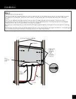
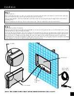
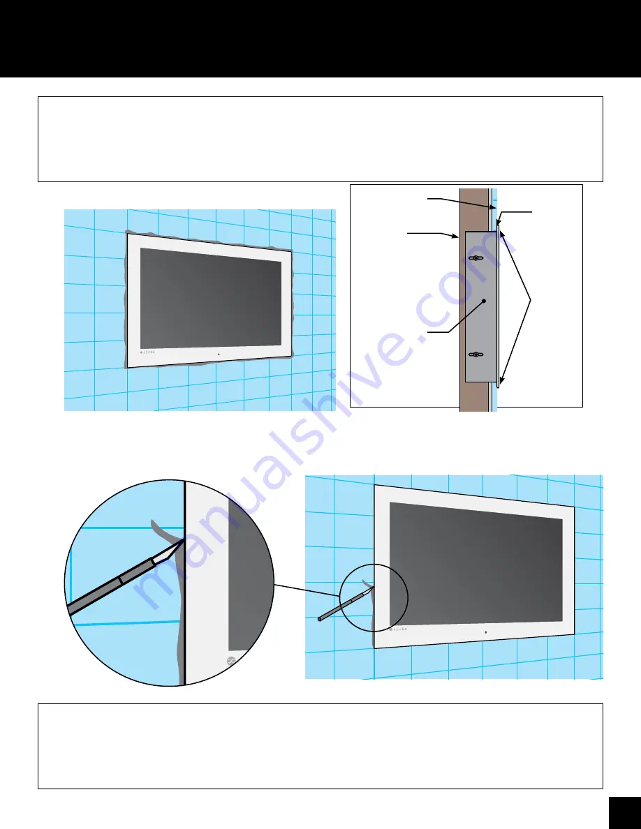
FINISHED 

WALL

FRAMING 

MEMBER

NOTE: 

GLASS 

FACE-

PLATE 

SEALS 

DIRECTLY 

TO 

FINISHED 

WALL 

SURFACE

SEALANT 

CREATES 

WATER-

TIGHT 

SEAL

COMPLETELY 

INSTALLED 

BACK BOX AND 

TV ASSEMBLY

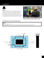
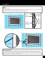
19" GLASS DIMENSION: 13   "

27" GLASS DIMENSION: 17   "  

19" WALL OPENING: 12   "

27" WALL OPENING: 16   "  

19" WALL OPENING: 18   "

27" WALL OPENING: 27   "  

19" GLASS DIMENSION: 19"

27" GLASS DIMENSION: 28"  

19" TOTAL DEPTH: 3    "

27" TOTAL DEPTH: 3"  

19" GAP     "

27" GAP     "

19" GAP      "

27" GAP     "

1 4

716

1 4

3 4

3 16

716

1 2

1 8

78

78

3

16

Installation

Step 5

Remove excess sealant.
Wipe drippping or excessive sealant. Allow waterproof sealant 24 hours to cure at 72 degrees Fahrenheit before exposing to moisture, 

or follow recommended time and temperature designated by sealant instructions.
Once fully cured, use a razor blade or utility knife to carefully remove excess sealant.

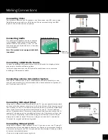
Removing the Unit

If the unit needs to be removed from the wall, essentially reverse the installation steps, starting with cutting the sealant. We 

recommend breaking the seal by side-cutting the sealant with a thin and durable line (such as a braided fishing line) and sawing 

back-and-forth between the glass face and wall. Then remove the TV from the back box. Disconnect all wires from the TV. Feed the 

power and other A/V electrical cords back through the pass-through port on the back box. Unscrew the framing members holding the 

backbox in place. Remove the back box from the wall opening.

Summary of Contents for Hydra IWT-19.6

Page 1: ...AL WWW SEURA COM 19 INCH AND 27 INCH TVS Hydra Indoor Waterproof Television MODEL NUMBER IWT 19 6 IWT 27 6 WARRANTY REGISTRATION REGISTER FOR EXTRA BENEFITS Activate within 30 days of purchase seura com activate ...

Page 2: ...te Control Functions 8 Installation 9 12 Making Connections 13 On Screen Display Menu OSD 14 17 Input Source Selection 14 Video Settings 14 Advanced Video Settings 15 Audio Settings 15 TV Settings 16 Setup Menu 16 Parental Menu 17 Media Support 18 Troubleshooting 18 Control 19 RS 232 Settings and IR Commands 19 Warranty 19 Contents ...

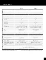
Page 3: ... Type A Firmware 5V Only 1 x Type A Firmware 5V Only RS 232 1 x 9 pin DB9 Female 2 5mm connector dongle included 1 x 9 pin DB9 Female 2 5mm connector dongle included IR 1 x 3 5mm Input Mono 4 x 3 5mm Output Mono 1 x 3 5mm Input Mono 4 x 3 5mm Output Mono AUDIO PC AUDIO IN 1 1 LINE OUT 2 x 3 5mm Jack 1 powered 1 unpowered 2 x 3 5mm Jack 1 powered 1 unpowered PHOENIX TYPE SPEAKER OUTPUT 2 x 5W 8Ω ch...

Page 4: ...easily accessible The TV should be connected to a grounded GFCI protected main socket outlet WARNING If you manipulate against the recommended usage serious injury or death to user may result NOTE THE POWER SUPPLY MUST NOT BE MOUNTED INSIDE A WALL CAVITY To protect against electric shock do not immerse the power cord power plug or product in water or other liquid Do not overload AC outlets or exte...

Page 5: ...lling and during use of this product basic safety precautions should always be followed to reduce the risk of fire electric shock and or injury to persons including the following Inspect the desired location for installation and be aware of all electrical wiring pathways water pipes gas lines or other potentially hazardous conditions that may exist to protect from accidental damage during creation...

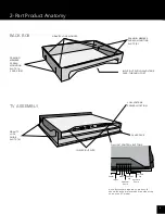
Page 6: ...CREW MOUNTING SLOTS 4 LOW VOLTAGE POWER LOCATION ON UNIT CONTROL BUTTONS GLASS FACE GRAVITY LOCK GUIDE SLOTS 4 GRAVITY LOCK MOUNTS INPUTS OUTPUTS BACK BOX TV ASSEMBLY Power Menu Channel Down Channel Up Volume Down Volume Up Input Note Buttons are labeled on product 19 shown Buttons are located on the side of the unit on the 27 model ...

Page 7: ...The device is factory set to the optimal operating voltage see Technical Specification Use only power cords and plugs that are suitable for your local electrical outlets Install the power cords in such a way that it does not obstruct anyone Ensure that the cable is not clamped and that it cannot be pulled out accidentally from the power adapter Do not install the power cords in the proximity of he...

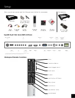
Page 8: ...Controls Exit Menu Mute Turns On or Off TV Audio Channel Control Volume Control Last Recall Last Channel Numerical Keypad Waterproof Remote Functions Resource Information USB DC 5V 0 5A HDMI 2 Input HDMI 1 Input VGA Input Component Input RS 232 Input S Video Input VGA Audio Input Composite Input IR Input Power Adapter Input Audio Variable Line Out Powered IR Output RF Coaxial Antenna Cable Input S...

Page 9: ...at the sole discretion of the installer and release Séura of all liability Read all installation instructions before beginning installation Scan to watch the 2 minute installation video 19 GLASS DIMENSION 13 27 GLASS DIMENSION 17 19 WALL OPENING 12 27 WALL OPENING 16 19 WALL OPENING 18 27 WALL OPENING 27 19 GLASS DIMENSION 19 27 GLASS DIMENSION 28 19 TOTAL DEPTH 3 27 TOTAL DEPTH 3 19 GAP 27 GAP 19...

Page 10: ... not overtighten mounting hardware Back box should fit snuggly between framing members If the fit is poor and overtightening occurs the back box may deform resulting in a poorly sealed installation If the back box doesn t fit well between framing members shim the framing members for a square and stable fit Feed power and other desired A V and electrical cords through the pass through port from ins...

Page 11: ...llation Step 4 Apply sealant and install TV assembly Generously apply 1 8 bead of supplied waterproof sealant to the outer lip of the glass face that surrounds the black metal housing Apply the sealant as close to the edge as possible With the sealant around the glass insert the TV assembly into the back box mounting that has been already installed Ensure gravity lock mounts fully engage Slowly co...

Page 12: ...hrenheit before exposing to moisture or follow recommended time and temperature designated by sealant instructions Once fully cured use a razor blade or utility knife to carefully remove excess sealant Removing the Unit If the unit needs to be removed from the wall essentially reverse the installation steps starting with cutting the sealant We recommend breaking the seal by side cutting the sealan...

Page 13: ... IR output terminals located on the TV For most devices use an IR emitter with a 3 5mm mono plug Attach the IR emitter side to the IR receiver of the device to be controlled and attach the 3 5mm mono plug to the TV s IR output Alternately if the device being controlled has 3 5mm IR input simply use a male to male 3 5mm mono plug to connect the TV and device IR output tip is signal and sleeve is gr...

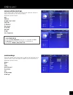
Page 14: ... arrows until the desired Input Source is highlighted 4 Press OK to confirm selection of the chosen input and clear the Input Source list from the screen or press again to switch through the signal inputs 5 Press to close the Input Source list without selecting an alternative source Video Settings The Video Settings menu offers options to enhance and refine the image characteristics of your Séura ...

Page 15: ...amma Color Temperature COLOR TEMPERATURE Within the Color Temperature menu you can customize the Color Temperature of the picture according to your preferences Your options Standard Warm User Cool OSD cont Audio Settings The Audio Settings menu offers options to enhance and refine the sound characteristics of your Séura television based on personal preferences Adjustment options include Balance Ba...

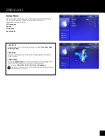
Page 16: ... you can determine a timespan after which the Séura television will turn off automatically Your options Off 10 20 30 40 50 60 90 120 minutes The Sleep Timer can also be activated and deactivated directly with the remote control Setup Menu The Setup Menu offers options to determine fundamental settings of your Séura television based on personal preferences Adjustment options include OSD Language Ca...

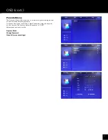
Page 17: ...program viewing based on various national rating systems To access the menu enter the 4 digit Password using the keypad on the remote The factory default password is 0000 Adjustment options include OSD cont Program Block Change Password Clean All or reset settings ...

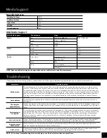
Page 18: ...onnected and that the connection pins are not bent or damaged Press Menu on your remote control you should see the OSD menu Check your settings for misconfigurations and adjust accordingly Alternatively perform a factory reset to restore the television to its default settings If the problem still exists contact customer service Low or no sound Press Volume Up and or Volume Down on your remote cont...

Page 19: ...site www seura com warranty If the current Séura warranty policy is after your product purchase date please contact Séura Customer Support to request warranty documentation from the date of your purchase For additional customer support please contact Séura Toll Free 1 800 957 3872 Monday Friday 8 00 am 4 30 pm Central Time Website www seura com support CONTROL DOCUMENTATION To access current contr...

Reviews: