13
142 x 208 mm
Do not tighten the screws too tightly to avoid damaging
the glass and handle.
Installation
∙ The appliance should be set up in a well-ventilated, dry
room.
∙ Do not use the appliance outdoors.
∙ Ensure that the plug is accessible and can be removed from
the wall socket at any time.
∙ Do not expose the appliance to direct sunlight, and do not
position it next to any heat sources (radiators, cookers
etc). If this cannot be avoided, however, suitable insulation
must be in installed between the heat source and the unit.
∙ The unit must not be installed inside a cabinet, nor directly
below a hanging cupboard, shelf or similar object.
∙ If the unit is installed next to a wall, a minimum lateral
distance of 10 mm is necessary for the door to fully open.
∙ If the floor is uneven, the adjustable feet on the unit can be
used to compensate and ensure optimum stability.
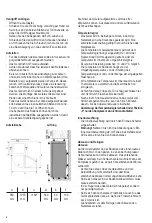
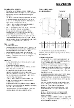
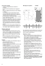
Set-up dimensions
Ventilation
A
B
C
D
E
F
950
mm
1053
mm
>180°
540
mm
30
mm
100
mm
The heated air around the rear of the unit must be able to
circulate freely. Therefore, ensure that the air circulation is
not obstructed.
Temperature control
∙ The unit is activated by connecting it to the mains. It is
only switched off completely when the plug is removed
from the wall socket.
∙ The temperature in the refrigerator cabinet can be
adjusted by setting the temperature control (0-7).
Turning the control clockwise will decrease the
temperature, while turning it anti-clockwise will increase
it.
∙ The temperature can be set within a 10 to 0°C range.
∙ The temperature in the cabinet largely depends on
factors such as the ambient temperature, the setting and
the number of bottles stored.
∙ We recommend using a thermometer to check the actual
temperature inside the cabinet and make adjustments
as necessary.
∙ Always ensure that the door is properly closed and that
the seal is not obstructed by bottles stored inside the
cabinet.
∙ It may take 3 to 5 minutes for the appliance to turn back
on after a power failure or when the appliance has been
disconnected from the mains.
∙ Note: With the temperature control in position ‘0’,
only the compressor is switched off, while the fan is
still running.
Interior lighting
∙ The interior light can be switched on by means of the
separate On/Off switch.
∙ Caution: Do not remove the cover of the interior LED
light. If there should be any malfunction, please contact
the customer service for assistance.
Defrosting and cleaning
Defrosting
During operation, you may notice a build-up of frost around
the integral evaporator sealed into the rear of the inside
cabinet. This layer of frost will start melting when the
compressor is not working. Through a system of hoses,
the melt-water drains into the collection tray below the
compressor, where it will be absorbed into the surrounding
air.
∙ To enable the melt-water to drain freely, always ensure
that the channel and discharge opening in the cabinet
are free of any blockage.
∙ Any water collecting in the bottom should be removed.
∙ Typically, the appliance requires no defrosting and should
only be cleaned.
∙ If thick frost forms, however, defrost the appliance when
the frost layer reaches a thickness of 2 mm.
∙ Always unplug the appliance before cleaning or
defrosting.
∙ Set the temperature control knob to “0” and leave the
door open. Defrosting of the appliance causes the
thawing water to collect at its bottom.
∙ Warning! Do not use any other mechanical devices or
other means, e.g. heaters, to speed up the defrosting.
Cleaning
∙ Do not pour water over or inside the unit.
∙ Do not use aggressive cleaning detergents or those
containing alcohol. Also, do not use electrical devices
such as steam cleaning devices for defrosting or
cleaning.
∙ For frequent cleaning we recommend the use of warm
water with some mild detergent.
∙ The cabinet should be cleaned once a month.
Summary of Contents for FKS 8840
Page 9: ...9...
Page 77: ...77 CE 60 GR...
Page 78: ...78 R600a 25 R600a...
Page 79: ...79 2 LED LED...
Page 81: ...81 0 7 10 0 C 3 5 0 On Off LED 2 mm 0...
Page 82: ...82 30 30 30 4 R600a C5H10 Severin Elektroger te GmbH R hre 27 59846 Sundern KS 0...
Page 84: ...84 Schaltplan Circuit diagramm...
Page 85: ...85...
Page 86: ...86...
Page 87: ...87...

