Installation
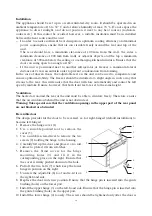
The appliance should be set up in a well-ventilated, dry room. It should be operated in an
ambient temperature of 16 to 32 °C and a relative humidity of max. 70 %. Do not expose the
appliance to direct sunlight, and do not position it next to any heat sources (radiators,
cookers etc). If this cannot be avoided, however, a suitable insulation must be in installed
between the heat source and the unit.
- In order to ensure sufficient heat dissipation, optimum cooling efficiency and minimal
power consumption, ensure that air can circulate freely around the rear and top of the
unit.
The rear should have a minimum clearance of 100 mm from the wall, the sides a
minimum clearance of 200 mm from walls or adjacent objects, and the top a minimum
clearance of 300 mm below the ceiling or overhanging kitchen furniture. Ensure that the
door can swing open to an angle of 160°.
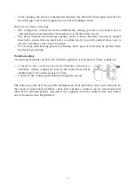
- If the unit is positioned next to another refrigerator or freezer, a minimum lateral
distance of 2 cm is essential in order to prevent condensation from forming.
In the case of uneven floors, the adjustable feet on the unit can be used to compensate and
ensure optimum stability. The freezer should be installed at a slight angle in such a way that
it leans to the rear: this will ensure that the door will close automatically and cannot be left
open by mistake. Ensure, however, that both front feet are set to the same height.
Ventilation
The heated air around the rear of the unit must be able to circulate freely. Therefore, ensure
that the air circulation behind the unit is not obstructed.
Warning: Take special care that the ventilation openings in the upper part of the rear panel
are not blocked or obstructed
Reversible door
The design provides for the door to be reversed, i.e. for right-hinged (default installation) to
become left-hinged.
1. Remove the hinge cover (1).
2. Use a suitable pointed tool to remove the
cover (5).
3. Use a suitable screw-driver to remove the two
screws (2) holding the hinge to the housing.
4. Carefully lift up the door and place it on a soft
surface to protect it from scratches.
5. Remove the blind covers for the hinge
mounting holes (9) and fit it in the
corresponding place on the right. Ensure that
the cover is firmly pushed down into the hole.
6. Pull off the two bolts (7) which keep the lower
hinge in position on the right.
7. Unscrew the adjustable (8) foot and re-fit it on
the right-hand side.
8. Replace the door in its new position. Ensure that the hinge pin is inserted into the guide
bushing (hole) on the lower part.
9. Install the upper hinge (3) on the left-hand side. Ensure that the hinge pin is inserted into
the guide bushing (hole) on the upper part.
10. Install the lower hinge (4) loosely. The screws should be tightened only after the door is
13
1
2
3
4
6
7
5
9
8
Summary of Contents for KS 9814 -
Page 83: ...2 R600a 83...
Page 84: ...3 5 C5H10 R 600 a 84...
Page 85: ...1 2 3 4 5 6 7 8 16 32 C 70 100 200 300 160 2 E 85...
Page 86: ...1 1 2 5 3 2 4 5 9 6 7 7 8 8 9 3 10 4 11 5 12 1 7 20 4 0 86 1 2 3 4 6 7 5 9 8...
Page 87: ...14 4 1 3 4 7 E 87...
Page 88: ...3 4 5 0 J J 2 88...
Page 89: ...J 89...
Page 90: ...30 90 E 0 E...
Page 91: ...KS KS 9814 94 2 A kWh 24 0 39 kWh 143 50 45 5 N C 16 32 24 0 8 490 x 500 x 495 22 C5H10 91...
Page 92: ...N 2 R600a 92 RUS...
Page 93: ...3 5 C5H10 R600a 93...
Page 94: ...1 2 3 4 5 6 7 8 16 32 C 70 100 200 300 160 2 94...
Page 95: ...1 1 2 5 3 2 4 5 9 6 7 7 8 8 9 3 10 4 11 5 12 1 7 20 4 0 95 1 2 3 4 6 7 5 9 8...
Page 96: ...14 4 1 3 4 7 96...
Page 97: ...3 4 5 0 2 97...
Page 98: ...98...
Page 99: ...2 30 99 0...
Page 100: ...5 Severin 2 6 8 KS 100...
Page 101: ...2 KS 9814 94 2 EC A 0 39 143 2 50 45 5 N C 16 32 0 8 490 x 500 x 495 22 C5H10 101...
Page 104: ...I M No 8096 0000...


