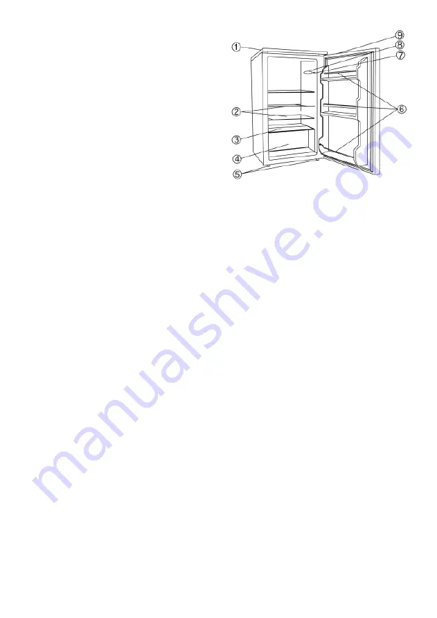
Familiarisation
1. Top
panel
2. Glass
shelves
3. Lower glass enclosure
4. Vegetable
compartment
5. Adjustable
feet
6. General and bottle storage
7. Temperature
control
8. Interior
lighting
9. Grip
recess
Before using for the first time
Remove any exterior and interior packaging materials completely, including the adhesive strips.
Before it is connected to the mains, the unit must be thoroughly checked for transport damage,
including its power cord.
Clean the unit as described in the section
De-frosting and cleaning
.
To ensure proper functioning, wait for about 2 hours before connecting the unit and switching it
on after it has been positioned.
When the unit is first switched on, a slight ‘new’ smell may be noticed. However, this will
disappear once the cooling process has begun.
Installation
The appliance should be set up in a well-ventilated, dry room.
It should be operated in conditions where the relative humidity is no more than 70 %.
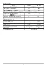
The product data sheet contains details of the ambient temperature range suitable for this
appliance.
Do not use the appliance outdoors.
Ensure that the plug is accessible and can be removed from the wall socket at any time.
Do not expose the appliance to direct sunlight, and do not position it next to any heat sources
(radiators, cookers etc). If this cannot be avoided, however, suitable insulation must be in installed
between the heat source and the unit.
The unit must not be installed inside a cabinet, nor directly below a hanging cupboard, shelf or
similar object.
Ensure that the door can swing open to an angle of 160°.
In the case of uneven floors, the adjustable feet on the unit can be used to compensate and ensure
optimum stability.
Ventilation
Ensure that there is enough space around the unit so that the air circulation round and behind it is
not obstructed. (Rear and sides 5 cm, top 10 cm.)
Reversible door
If required, the door may be reversed, i.e. from right-hinged (default installation) to left-hinged.
Warning:
Always disconnect the unit from the mains before any maintenance or repair work is
carried out.
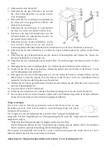
1. Remove the two screw covers (11) and the screws (10).
13
Summary of Contents for KS 9825
Page 83: ...R600a 83...
Page 84: ...R600a 84...
Page 85: ...1 2 3 4 5 6 7 8 9 2 70 160 5 cm 10 cm 85...
Page 86: ...1 11 10 2 9 3 6 5 4 5 7 6 5 7 8 1 2 9 10 4 11 2 12 13 5 3 14 15 9 16 10 11 9 17 86...
Page 87: ...30 3 5 0 15 W 3 5 4 1 3 5 7 87...
Page 88: ...88...
Page 89: ...0 45 2 89...
Page 91: ...R600a RUS 91...
Page 92: ...92...
Page 93: ...R600a 1 2 3 4 5 6 7 8 9 2 70 160 93...
Page 94: ...5 10 1 11 10 2 9 3 6 5 4 5 7 6 5 7 8 1 2 9 10 4 11 2 12 13 5 3 14 15 9 16 10 11 9 17 30 3 94...
Page 95: ...5 0 15 3 5 4 1 3 5 7 95...
Page 96: ...0 96...
Page 97: ...45 2 Severin 2 a x KS 97...
Page 100: ...I M No 8560 0000...

