7
b – Valves
-
The one-way valve
(G, J): the boat uses the one-way valve. This simple, rugged one-way valve makes inflation
easy. The inner valve design allows air to flow into the hull but not out, and outer valve cap makes the seal
permanent. The plastic stem on the inner valve allows the boat to be deflated. Push in and turn to release air.
Make sure the plastic stem is in the “out” position for inflation.
-
The rear drain valve
(U)
:
the boat is equipped with a rear drain valve to drain water from the inside of the hull.
Do not fill the rear drain valve with air.This rear drain valve has a plug to keep it totally watertight when not in
use. To use the drain valve, remove the plug and gently accelerate to get your boat in a bow-high attitude.
Water will rush to the rear of the boat and drain out the valve. Replace plug when finished. Another option is to
pull the boat up on a beach or boat ramp and drain on land.
c – Pump
Your boat is supplied with a high pressure double action hand piston pump which can deliver a pressure up to 1
bar / 14.5 PSI. We firmly recommend you always carry your hand piston pump on board, for safety
Inflate your boat using either the pump supplied with it or an electric inflator. An electric inflator inflates rapidly to
moderate pressure, but boat inflation must be finished using the supplied pump.
5.3.2
Inflation sequence
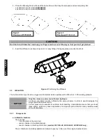
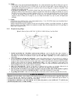
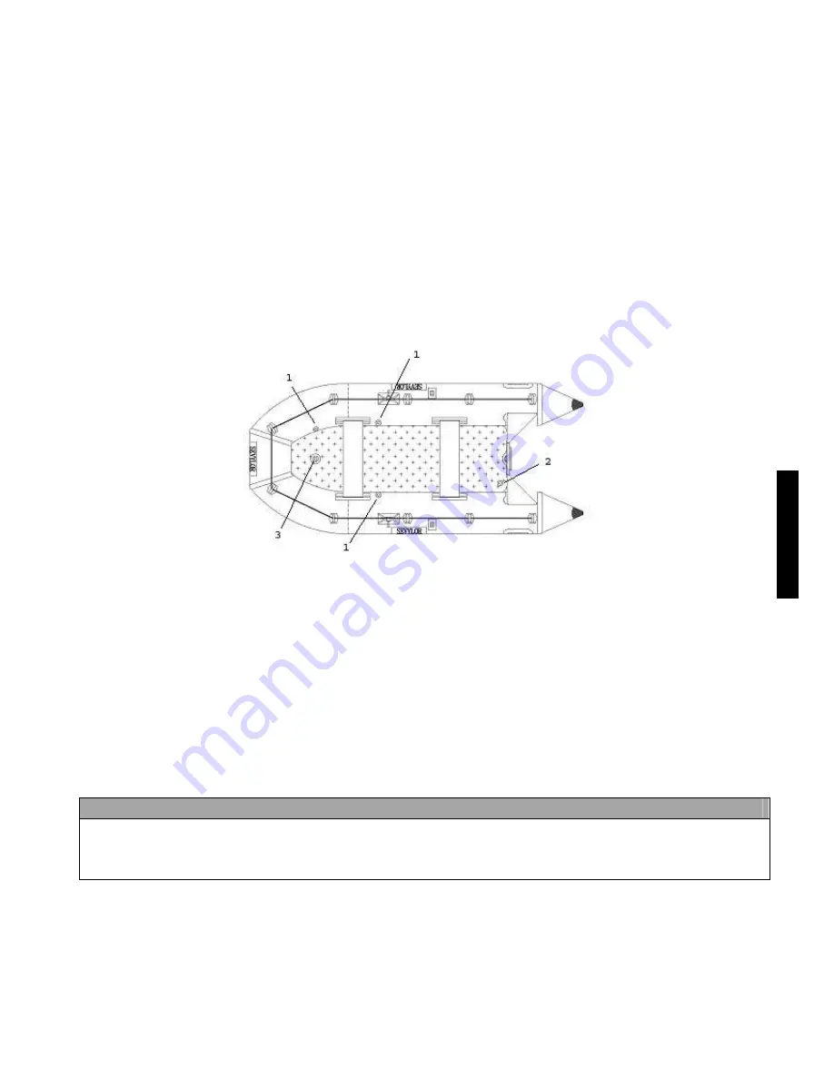
Figure 5 :
(Illustration model SV270S-HF, SV320S-HF, SV350S-HF with Drop Stitch Floor)
1.
First inflate the 3 air chambers of the boat body:
open the caps of the valves (1) and fix the end of the pump
tube on the valve inlet (use the appropriate end fitting for the valve). Inflate the 3 air chambers to 90% of the
required pressure (about
180 mbar/2.6 PSI)
–
refer to the pressure gauge user manual
.
2. Models
SV270S-HF, SV320S-HF, SV350S-HF:
place the Drop Stitch bottom on the bottom of the boat, making
sure that the edges are under the curved sides of the air chambers inside the boat. The valve (3) of the inflatable
keel must be located opposite the hole provided for it in the Drop Stitch bottom. Inflate the Drop Stitch bottom (2)
to a pressure of
420 mbar
(7 PSI)
-
refer to the pressure gauge user manual
. Then inflate the keel until the Drop
Stitch bottom is properly in position. You may have to stand on the Drop Stitch bottom to make sure it goes into
the correct position.
3.
Install the benches (H):
slide the plastic tabs (on the underside of the benches) into the small plastic cylinders
on the side air chambers.
4.
Finish inflation ; inflate all hull chambers to 100 %: 200 mbar / 3 PSI. And inflate keel to 80 % of max.
pressure : 160 mbar / 2.3 PSI. Please refer to the “Instructions for the manometer”
5.
After inflation, fit all the valves cap tight
(clockwise).
WARNING !
If you leave your boat exposed to the hot sun, deflate slightly the main chambers.
Extreme sunshine (ultra-violet rays) over a long period may accelerate ageing the materials of your boat.
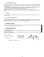
1.1.1. The ambient temperature affects the tube’s internal pressure : a variation of 1°C causes a variation of
the pressure in the tube of +/- 4 mbar (0,6 PSI).
5.3.3
Pressure regulation
Overpressure: deflate until you reach the recommended pressure.
Drop of pressure: inflate again slightly.
E
N
G
L
I
S
H
Summary of Contents for ST270W-HF
Page 178: ...178 5 3 3 6 6 1 6 2 6 3 7 7 1 2 7 2 V...
Page 179: ...179 7 3 7 4 7 5 50 8 9 D D C 6...
Page 180: ...180 10 10 1 10 2 10 3...
Page 181: ...181 10 4 11 12 1 2 3 4 Drop Stitch 5 6...
Page 182: ...182 13 60 18 C 25 C 1 5 cm 2 5 3 3 5 4 12 14 2 ii iii iv ADG...
Page 198: ...198 5 3 3 6 MOTOP 6 1 6 2 6 3 7 7 1 2 7 2 V...
Page 199: ...199 7 3 7 4 7 5 50 8 9 D D C 6...
Page 200: ...200 10 10 1 10 2 10 3...
Page 201: ...201 10 4 11 12 1 2 3 Drop Stitch 4 2 5...
Page 202: ...202 13 60 18 C 25 C 1 5 2 5 3 3 5 4 12 14 2 i ii iii iv ADG...


