5
Electrical installation
Connecting the motor and the encoder system via plug connector SM./SB./SH.
Operating Instructions – CM3C63 – 100
29
INFORMATION
The connector should only be rotated to install and connect the motor. Do not turn
the plug connector regularly once it has been installed.
INFORMATION
To protect the motor protection devices or the brake control from damage, you must
not route unshielded supply cables alongside switched-mode power cables.
Shielded supply cables may be routed together with switched-mode power lines in
one cable.
Switched-mode power cables are:
•
Output cables from servo inverters, converters, and brake units
•
Supply cables for braking resistors and similar options
5.5.2
Type designation of plug connectors at the cable side
The following table describes a type designation:
Example: SM12
S
S:
Connector
M
M
: Motor
B
: Brakemotor
H
: Hybrid design (power rating and signals)
1
1
: Connector size 1 (1.5 – 4 mm
2
)
B
: Connector size 1.5 (6 – 16 mm
2
)
2
Cross section
1
: 1.5 mm
2
,
2
: 2.5 mm
2
,
4
: 4 mm
2
,
6
: 6 mm
2
10
: 10 mm
2
,
16
: 16 mm
2
5.5.3
Connector positions with two-cable technology (SM1/SB1, SMB/SBB)
The right-angle plug connectors SM1/SB1 and SMB/SBB can be rotated to achieve
any required position.
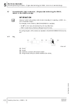
The following figure shows examples of the differently adjusted plug connectors SM1/
SB1, SMB/SBB:
29125640203
26870460/EN – 05/2021


