background image

5

Electrical installation

Connecting the plug connectors – Single-cable technology for CM3C.. motors in encoderless design

Operating Instructions – CM3C63 – 100

44

5.7

Connecting the plug connectors – Single-cable technology for CM3C..
motors in encoderless design

INFORMATION

Using an inverter with suitable control mode is mandatory for operating a CM3C.. mo-
tor in encoderless design.

The following control modes by SEW‑EURODRIVE are available:

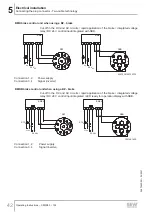
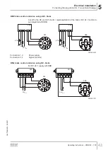
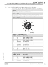
ELSM

®

 control mode (Encoderless Synchronous Machine)

PMVC control mode (Permanent Magnet Vector Control)

The wiring diagrams of the motors are available in the SEW‑EURODRIVE Online Sup-
port.

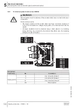
5.7.1

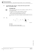
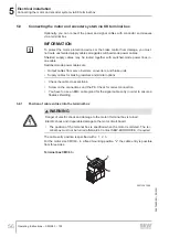
Key

[A]

[C]

[B]

[A]

[D]

[B]

8790995467

[A] View A
[B] View B
[C] Customer connector with socket contacts
[D] Flange socket with pin contacts installed at the factory

26870460/EN – 05/2021

Summary of Contents for CM3C63-100

Page 1: ... 26870460_0521 Drive Technology Drive Automation System Integration Services Operating Instructions Synchronous Servomotors Medium Inertia CM3C63 100 Edition 05 2021 26870460 EN ...

Page 2: ...SEW EURODRIVE Driving the world ...

Page 3: ...cture 14 3 1 Basic structure 14 3 2 Nameplate and type designation 15 3 3 Designs and options 18 3 4 Functional safety 20 4 Mechanical installation 21 4 1 Before you start 21 4 2 Motor installation notes 21 4 3 Installation tolerances 23 4 4 Screw sizes and tightening torques for flange mounting 23 5 Electrical installation 24 5 1 General information 24 5 2 Additional regulations 26 5 3 Wiring not...

Page 4: ... BK brake 95 7 4 Notes on the BZ brake 95 7 5 Cleaning 99 7 6 Connection cable 99 8 Technical data 100 8 1 Boundary conditions 100 8 2 Technical data of the BK brakes 100 8 3 Technical data for the BZ and BZ D brakes 103 8 4 Characteristic safety values of BK brakes 108 8 5 Characteristic safety values of BZ brakes 108 9 Malfunctions 109 9 1 General information 109 9 2 Servomotor malfunctions 109 ...

Page 5: ... 1 Additional information This documentation contains additional information on the product or optional compo nents Wiring diagrams provided with the motor Addendum to the operating instructions Safety Encoder and Safety Brake 1 3 Structure of the safety notes 1 3 1 Meaning of signal words The following table shows the grading and meaning of the signal words for safety notes Signal word Meaning Co...

Page 6: ...rical voltage No access for persons with pacemakers or implanted defibril lators Warning of hot surfaces Warning of risk of crushing Warning of automatic restart 1 3 3 Structure of embedded safety notes Embedded safety notes are directly integrated into the instructions just before the de scription of the dangerous action This is the formal structure of an embedded safety note SIGNAL WORD Type and...

Page 7: ... under limited warranty Read the documentation before you start working with the product 1 6 Product names and trademarks The brands and product names in this documentation are trademarks or registered trademarks of their respective titleholders 1 7 Copyright notice 2021 SEW EURODRIVE All rights reserved Unauthorized reproduction modifica tion distribution or any other use of the whole or any part...

Page 8: ...sure that all of the work listed in the following may be carried out only by qualified specialists Setup and installation Installation and connection Startup Maintenance and repairs Shutdown Disassembly Ensure that the persons who work on the product pay attention to the following regula tions conditions documentation and information National and regional safety and accident prevention regulations...

Page 9: ...ectives and laws specified in this documentation The persons must have the express authorization of the company to operate pro gram parameterize label and ground devices systems and circuits in accordance with the standards of safety technology Instructed persons All work in the areas of transportation storage operation and waste disposal must be carried out by persons who are trained appropriatel...

Page 10: ...To avoid cutting injuries remove the retaining straps carefully from the product and wear suitable protective clothing if necessary The open keyway has sharp edges Insert the key in the keyway and pull a pro tective tubing over the shaft If the product weights more than 40 kg use suitable lifting equipment such as belts Always use lifting eyebolts and lifting eyes if available Tighten lifting eyeb...

Page 11: ...ically skilled persons Always adhere to the 5 safety rules for working on electrical components Disconnect Secure the drive against restart Check that no voltage is applied Ground and short circuit it Cover or safeguard neighboring live parts When the device is switched on dangerous voltages are present on all power con nections as well as on any connected cables and terminals This is also the cas...

Page 12: ... shorter than the minimum values according to IEC 60664 and national regula tions With low voltage the distances should be no shorter than the following values in compliance with IEC 60664 Nominal voltage VN Distance 500 V 3 mm 690 V 5 5 mm The terminal box must be free from foreign objects dirt and humidity Unused cable entry openings and the connection box itself must be sealed so that they are ...

Page 13: ... not disconnect power connections during operation Do not connect power connections during operation Mechanical blocking or internal protective functions of the product can cause a motor standstill Eliminating the cause of the problem or performing a reset may result in the drive restarting automatically If for safety reasons this is not permitted for the drive controlled machine first disconnect ...

Page 14: ...ns 3 1 1 Structure of the CM3C motor without brake INFORMATION The following figures are merely examples The actual gear units may deviate from the figures depending on the design and size The following figure shows an overview of the motor components 1 4 3 2 6 5 28956583947 1 Output shaft with key 4 Housing 2 Flange 5 Power plug connector 3 Lifting eyebolt 6 Signal plug connector 26870460 EN 05 2...

Page 15: ...Type designation 2 Serial number 3 Standstill torque Variable torque Rated speed Mounting position 4 Dynamic limit torque of the servomotor Maximum permitted speed Degree of protection according to IEC 60034 5 5 Standstill current Voltage at the open terminals of the motor at rated speed Mass 6 Maximum permitted current Ambient temperature Thermal class 7 System voltage voltage of the supplying in...

Page 16: ... to state compliance with European guidelines such as the Low Voltage Directive SEW DRN90L4 1 5 kW 22785868 10 CEL mark showing energy efficiency in the Chinese grade classification CMIM logo to confirm compliance with technical regulations of the country Morocco 02 FS logo with 2 digit number for identification of installed functional safety motor options UR logo to confirm that UL Underwriters L...

Page 17: ...try Product label with QR code The QR code can be scanned You will be re directed to the digital services of SEW EURODRIVE There you have ac cess to product specific data documents and further services 3 2 2 Serial number The following table lists the structure of a serial number Example 01 77185696 09 0001 19 01 Sales organization 77185696 Order number 8 digits 09 Order item 2 digits 0001 Quantit...

Page 18: ... end E Shaft with push in pinion 3 3 2 Mechanical attachments Designation Option BK Permanent magnet holding brake BZ1 BZD1 2 Spring loaded holding brake with increased working capacity HR3 Manual brake release re engaging 1 Also available in design for functional safety 2 For a direct DC voltage supply 3 Available for BZ and BZD only 3 3 3 Temperature sensor temperature detection Designation Opti...

Page 19: ...3C63 100 19 Designation Option EK1H Single turn encoder HIPERFACE 1 Also available in design for functional safety CM3C servomotors are also available without encoder 3 3 5 Ventilation Designation Option VR Forced cooling fan for size CM3C71 100 26870460 EN 05 2021 ...

Page 20: ... verters Safety brake Safety encoder 01 X 02 X 04 X 07 X X 11 X X If the FS logo e g with the code FS 11 is present on the motor nameplate the com bination of safety encoder and safety brake is available at the motor If an FS logo is available adhere to the information specified in the corresponding documentation If the drive bears the FS logo on the nameplate adhere to the information in the fol ...

Page 21: ...unit operating instructions You have ensured that there are no oils acids gases vapors radiation etc present The aforementioned information refers to standard orders The requirements for spe cial designs might vary from the standard Refer to the order confirmation for deviating conditions Make sure that the drive is designed according to the ambient conditions Functional safety If the drive has th...

Page 22: ...n free and torsionally rigid support structure Use the screws and tightening torques specified in chapter Screw sizes and tight ening torques for flange mounting 2 23 during flange mounting Align the motor and the driven machine carefully in order to prevent the output shaft from being exposed to unacceptable strain Observe the permitted overhung and axial forces Do not jolt or hammer the shaft en...

Page 23: ...ssembly If necessary restore the anti corrosive paint coat Check that the degree of protection is maintained 4 3 Installation tolerances Shaft end Flanges Diameter tolerance according to EN 50347 ISO k6 Center hole according to DIN 332 shape DR Centering shoulder tolerance according to EN 50347 ISO j6 4 4 Screw sizes and tightening torques for flange mounting Use the screw sizes and tightening tor...

Page 24: ...nection This can result in severe or fatal injuries Each product must be secured with a ground connection Make sure to install the ground connection correctly Operate the product only with correctly connected protective earth even for short time measuring or test purposes WARNING Electric shock when disconnecting or connecting voltage carrying plug connectors This can result in severe or fatal inj...

Page 25: ...t accumulates in small quantities in the termi nal box Irritation of the respiratory tract and respiratory organs ü Wear a respirator of class FFP2 when performing work in the terminal box of brakemotors Avoid swirling of the brake abrasion Remove the brake abrasion with suitable extraction systems or damp cloths that bind dust The dust must not be blown out Make sure that there is adequate ventil...

Page 26: ...o protect the brake control system against interference do not route unshielded brake cables together with switched mode power cables Switched mode power cables include in particular Output cables from servo inverters converters soft start units and brake units Supply cables for braking resistors and similar options 5 3 2 Protecting the motor protection devices against interference Adhere to the f...

Page 27: ...brake release even if the control voltage has been switched off WARNING Unintentional ongoing brake release due to unrecognized malfunction of the brake control Severe or fatal injuries e g due to falling hoist or extended coasting Always disconnect all poles of the supply and control voltage for hoists and hoist like applications Ensure that a malfunction of the control input can be detected thro...

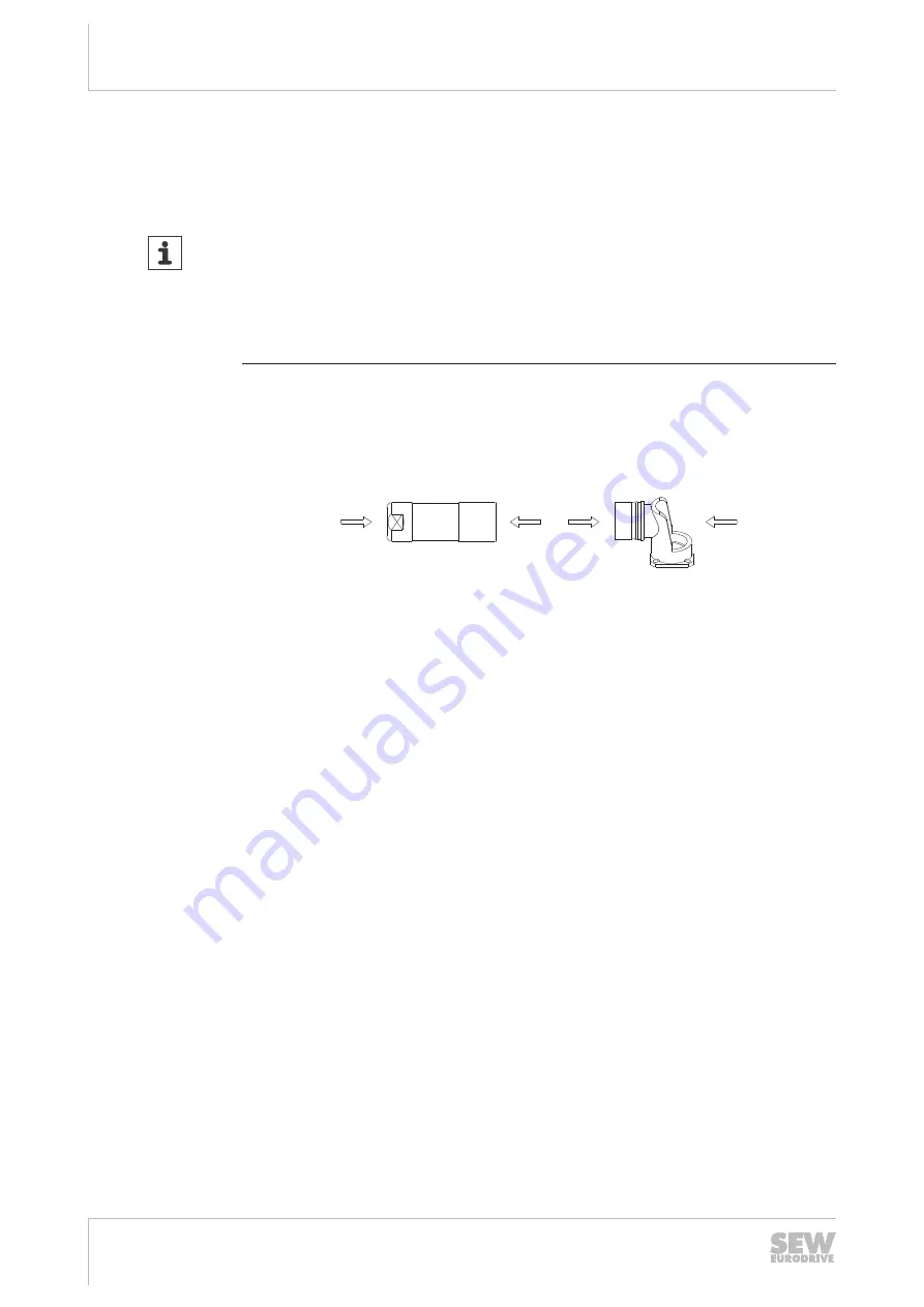
Page 28: ... Synchronous Machine PMVC control mode Permanent Magnet Vector Control All servomotors are equipped with quick lock right angle or radial connectors as stan dard SpeedTec 5 5 1 Notes regarding the connection of the power and signal cables via the connector system Power cables and signal cables are connected with adjustable right angle connectors as standard NOTICE Damage to the right angle connect...

Page 29: ...er cables are Output cables from servo inverters converters and brake units Supply cables for braking resistors and similar options 5 5 2 Type designation of plug connectors at the cable side The following table describes a type designation Example SM12 S S Connector M M Motor B Brakemotor H Hybrid design power rating and signals 1 1 Connector size 1 1 5 4 mm2 B Connector size 1 5 6 16 mm2 2 Cross...

Page 30: ...n the right angle connector only while the mating connector is plugged in Do not use pliers to adjust the right angle connector before connecting it 2 Plug the mating connector onto the right angle connector 3 Align the mating connector 4 Lock the mating connector by turning the union nut to a stop approx 90 Between plug connector and bushing is a gap of 2 mm 5 5 4 Connector positions with single ...

Page 31: ...power plug connector with without brake The following table shows information about this connection The wiring diagram of the plug connector depicts the contact end of the connections Function Power connection Connection type M23 TE Connectivity Intercontec Products series 923 SEW insert speedtec equipment coding ring without male Connection diagram C B A D 1 PE 3 4 Assignment for motor without br...

Page 32: ...ent for brakemotors with BZ BZ D brake Contact Signal Description A Reserved Do not connect B Brake BZ brake omitted for BZ D brake C Brake BZ brake D Brake BZ brake PE PE PE connection 1 U Motor connection phase U 3 W Motor connection phase W 4 V Motor connection phase V Wiring diagram SM1 SB1 with without BK brake Connect the shield to the metal housing of the connector The color code correspond...

Page 33: ...he metal housing of the connector The color code corresponds to the cables from SEW EURODRIVE D C B A 3 1 4 BU GNYE RD BK U1 V1 W1 D C B A 3 1 4 BK GNYE BK BK U V W BK 3 BK 2 13 14 15 BK 1 RD BU WH B 1 1 A 2 9007228536929291 1 BZ BZ D brake optional 2 Connection to rectifier from SEW EURODRIVE according to operating instructions For BZ D there is no port 14 contact B 26870460 EN 05 2021 ...

Page 34: ...ert speedtec equipment coding ring without male Connection diagram 1 2 PE W V U Assignment for motor without brake Contact Signal Description Reserved Do not connect Reserved Do not connect 1 Reserved Do not connect 2 Reserved Do not connect PE PE PE connection U U Motor connection phase U V W Motor connection phase W W V Motor connection phase V Assignment for brakemotors with BK brake Contact Si...

Page 35: ... code corresponds to the cables from SEW EURODRIVE V W U 1 2 BK V BK W BK 3 BK 1 BK U GNYE V W U 1 2 RD V1 BU W1 GNYE BK U1 RD BU 1 A 1 B 13 15 2 29282190731 1 BK brake optional 2 Connection to SEW rectifier according to operating instructions Wiring diagram SMB SBB with without BZ BZ D brake Connect the shield to the metal housing of the connector The color code corresponds to the cables from SEW...

Page 36: ...nsert SpeedTec equipment coding ring without male Connection diagram P 9 8 12 7 6 5 4 3 2 10 1 11 Assignment for motor with RH1M resolver Contact Signal Description 1 R1 Ref Reference 2 R2 Ref Reference 3 S1 Cos Cosine 4 S3 Cos Cosine 5 S2 Sin Sine 6 S4 Sin Sine 7 Reserved Do not connect 8 Reserved Do not connect 9 PK Motor protection 10 PK Motor protection 11 Reserved Do not connect 12 Reserved D...

Page 37: ...ry Wiring diagram Connect the shield to the metal housing of the connector The color code corresponds to the cables from SEW EURODRIVE 1 9 8 2 10 12 7 3 4 5 6 11 GY RD BU BNVT YE GN PK WHBK S2 sine S4 sine 1 9 8 2 10 12 7 3 4 5 6 11 BKWH RD YE BU R1 reference RDWH BK R2 reference S1 cosine S3 cosine B A PK BK PK RD 18014427791655691 Wiring diagram for signal plug connector AAK0H AK1H EK1H encoder ...

Page 38: ...6 5 Wiring diagrams of the brake control BK or BZ D brake BMV brake controller D C B A 3 1 4 BMV 1 2 3 4 13 14 15 SB1 K12 U DC 24 V IN DC 24 V 9007212241295115 Connection 1 2 Power supply Connection 3 4 Signal inverter Braking contactor BS or BZ D D C B A 3 1 4 BS SB1 24 VDC 1 2 3 4 5 12986690059 26870460 EN 05 2021 ...

Page 39: ...correct polarity of the brake power supply Check the polarity when replacing the brake With MOVIAXIS or MOVIDRIVE modular D C B A 3 1 4 SB1 24 VDC BGND DBØØ 9007207071783051 With third party in verters D C B A 3 1 4 SB1 24 VDC 12986696203 The brake must be protected from overvoltage e g by a varistor protection circuit in the following cases Operation on non SEW inverters If the brake is not direc...

Page 40: ...3 4 13 14 15 SB1 BME K12 UAC 1 2 3 4 13 14 15 SBB 2901967755 Cut off in the DC and AC circuits rapid application of the brake with SB1 SBB when using a BZ brake D C B A 3 1 4 V W U 1 2 BME K12 UAC 1 2 3 4 13 14 15 SB1 BME K12 UAC 1 2 3 4 13 14 15 SBB 2901969419 BMP brake rectifier when using a BZ brake Cut off in the DC and AC circuits rapid application of the brake integrated voltage relay with S...

Page 41: ...lication of the brake with SBB when using a BZ brake D C B A 3 1 4 V W U 1 2 BMH K12 UAC 1 2 3 4 13 14 15 SB1 BMH 1 2 3 4 13 14 15 SBB K12 UAC 2901974795 Cut off in the DC and AC circuits rapid application of the brake with SBB when us ing a BZ brake D C B A 3 1 4 V W U 1 2 BMH K12 UAC 1 2 3 4 13 14 15 SB1 BMH 1 2 3 4 13 14 15 SBB K12 UAC 2901976459 26870460 EN 05 2021 ...

Page 42: ... 14 15 SB1 BMK 1 2 3 4 13 14 15 SBB 24 VDC VAC 24 VDC 9007202156720139 Connection 1 2 Power supply Connection 3 4 Signal inverter BMKB brake control unit when using a BZ brake Cut off in the DC and AC circuits rapid application of the brake integrated voltage relay DC 24 V control input integrated LED ready for operation display with SBB D C B A 3 1 4 V W U 1 2 BMKB K12 UAC 1 2 3 4 13 14 15 SB1 BM...

Page 43: ... of the brake DC 24 V control in put integrated with SBB D C B A 3 1 4 V W U 1 2 BMV K12 1 2 3 4 13 14 15 SB1 BMV 1 2 3 4 13 14 15 SBB 24 VDC K12 24 VDC 24 VDC 24 VDC 2901984523 Connection 1 2 Power supply Connection 3 4 Signal inverter BSG brake control unit when using BZ brake For DC 24 V supply with SBB D C B A 3 1 4 V W U 1 2 BSG SB1 SBB 24 VDC 24 VDC 1 2 3 4 5 BSG 1 2 3 4 5 2901987211 2687046...

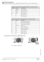
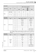
Page 44: ...ble control mode is mandatory for operating a CM3C mo tor in encoderless design The following control modes by SEW EURODRIVE are available ELSM control mode Encoderless Synchronous Machine PMVC control mode Permanent Magnet Vector Control The wiring diagrams of the motors are available in the SEW EURODRIVE Online Sup port 5 7 1 Key A C B A D B 8790995467 A View A B View B C Customer connector with...

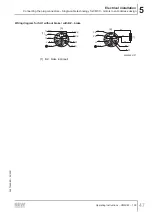
Page 45: ...n sert SpeedTec equipment coding ring without protected against contact Connection diagram U V W A B C D H L PE 34609095051 Assignment for motor without brake Contact Signal Description U U Motor connection phase U V V Motor connection phase V W W Motor connection phase W A Reserved Do not connect B Reserved Do not connect C Reserved Do not connect D Reserved Do not connect PE PE PE connection H H...

Page 46: ...otection Assignment for brakemotors with BZ brake in encoderless design No Name Function U U Motor connection phase U V V Motor connection phase V W W Motor connection phase W A Reserved Reserved B 14 Brake connection 14 C 13 Brake connection 13 D 15 Brake connection 15 PE PE PE connection H H Motor protection L L Motor protection Wiring diagram for SH1 without brake with BZ D BK brake BU RD RD GN...

Page 47: ...coderless design Operating Instructions CM3C63 100 47 Wiring diagram for SH1 without brake with BZ brake BU RD GNYE BK BK PK U 1 BU BK 3 BK W GNYE PK U W PK WH A PK B V D B A H L C V W U A C D H L B U W V BK U BK U RD V BK 1 15 13 BU W WH RD 14 BK 2 1 34644894731 1 BZ brake optional 26870460 EN 05 2021 ...

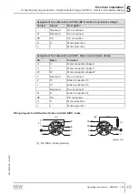
Page 48: ...ding ring without protected against contact Connection diagram 2 U PE N V H L 1 W Assignment for motor without brake Contact Signal Description U U Motor connection phase U V V Motor connection phase V W W Motor connection phase W 1 Reserved Do not connect 2 Reserved Do not connect Reserved Do not connect Reserved Do not connect N Reserved Do not connect PE PE PE connection H H Motor protection L ...

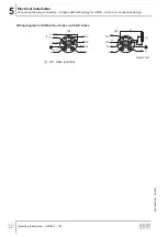
Page 49: ...rakemotors with BZ brake in encoderless design No Name Function U U Motor connection phase U V V Motor connection phase V W W Motor connection phase W 1 Reserved Do not connect 2 15 Brake connection 15 13 Brake connection 13 Reserved Do not connect N 14 Brake connection 14 PE PE PE connection H H Motor protection L L Motor protection Wiring diagram for SHB without brake with BZ D BK brake RD GNYE ...

Page 50: ...encoderless design Operating Instructions CM3C63 100 50 Wiring diagram for SHB without brake with BZ brake RD GNYE BU BK PK W 1 BU BK 3 BK 1 GNYE PK V 13 PK WH PK B BK U BK V BK U BK 2 15 14 RD V W 1 H L 2 U N V 2 1 H L V W U N BK W W U RD WH BU A 1 34644925963 1 BZ brake optional 26870460 EN 05 2021 ...

Page 51: ...olled directly via the brake output of a MOVIDRIVE modular application inverter BMV brake controller BMV 1 2 3 4 13 14 15 SH1 K12 U DC 24 V IN DC 24 V D B A H L C V W U A BK3 BK1 34755470603 Connection 1 2 Power supply Connection 3 4 Signal inverter Direct 24 V brake supply with non SEW inverters If the brake is not controlled via BMV brake control unit a contactor must be used that is suitable fo...

Page 52: ...RC element can be switched via the contactor DC 24 V 2 1 SHB A W 1 H L 2 U N V 1 2 D B A H L C V W U DC 24 V SH1 A 9007218586515979 1 Varistor 2 RC element Direct 24 V brake supply With MOVIDRIVE modular SH1 DC 24 V DGND DBØØ D B A H L C V W U A 34755725835 NOTICE Damage to the BK BZ D brake Possible damage to property It is essential that you observe the correct polarity of the BK BZ D brake supp...

Page 53: ... L 2 U N V SH1 A BME BME SHB A SH1 BK1 BK3 BK2 BK1 BK3 BK2 34756230539 Cut off in the DC and AC circuits rapid application of the brake with SH1 SHB K12 UAC 1 2 3 4 13 14 15 K12 UAC 1 2 3 4 13 14 15 D B A H L C V W U SH1 A W 1 H L 2 U N V SHB A BME BME BK1 BK3 BK2 BK1 BK3 BK2 34756241675 BMP brake rectifier Cut off in the DC and AC circuits rapid application of the brake integrated voltage relay w...

Page 54: ...apid application of the brake with SH1 and SHB BMH K12 UAC 1 2 3 4 13 14 15 SB1 BMH 1 2 3 4 13 14 15 SBB K12 UAC W 1 H L 2 U N V D B A H L C V W U A A BK1 BK3 BK2 BK1 BK3 BK2 34756321291 BMK BMKB brake control unit Cut off in the DC and AC circuits rapid application of the brake integrated voltage relay DC 24 V control input integrated LED ready for operation display with SH1 and SHB BMK K12 UAC 1...

Page 55: ...ke controller Cut off in the DC and AC circuits rapid application of the brake DC 24 V control in put integrated with SH1 SHB 24 VDC 24 VDC BMV K12 1 2 3 4 13 14 15 SH1 BMV 1 2 3 4 13 14 15 SHB 24 VDC K12 24 VDC D B A H L C V W U W 1 H L 2 U N V A A BK1 BK3 BK2 BK1 BK3 BK2 34756352523 Connection 1 2 Power supply Connection 3 4 Signal inverter 26870460 EN 05 2021 ...

Page 56: ...ake units Supply cables for braking resistors and similar options Check the cable cross sections Screw on the connections and the PE Check for correct connection You have to use an EMC cable gland for the signal cable entry in order to ensure a flawless shielding 5 8 1 Position of cable entries into the terminal box WARNING Danger of electric shock and damage to the motor if terminal box is turned...

Page 57: ... box CM3C71 100 3 2 1 X 29314123659 5 8 2 Connection cross section Motor Power connection Encoder resolver thermal motor protection Connection Maximum connection cross sec tion Cable entry Connection Cable entry CM3C63 Spring termi nals 4 mm2 M25 Spring terminals M20 CM3C71 CM3C80 CM3C100 M6 stud 10 mm2 M32 M16 26870460 EN 05 2021 ...

Page 58: ...minimum clearance of 4 mm to all uninsulated or voltage carrying parts of the terminal board and the eyelets All single conductors must be insulated using a cable jacket or an insulating tubing until they are connected to the terminal strip Make sure the insulating tubing cannot get out of place PE W V U 3a 4a 5a 10 9 8 7 6 5 4 3 2 1 PE W V U 3a 4a 5a 10 9 8 7 6 5 4 3 2 1 1 2 3 30661741323 Assignm...

Page 59: ... 1 R1 Ref Reference 2 R2 Ref Reference 3 S1 Cos Cosine 4 S3 Cos Cosine 5 S2 Sin Sine 6 S4 Sin Sine 7 8 9 PK Motor protection 10 PK Motor protection The connection diagram and signal logics of the RH1M resolver are identical for CMP and CM3C motors Due to the installation design the color coding of the cores might vary Assignment Terminal 3 Type No Connection Note Signal Encoder AK1H EK1H AK0H 1 co...

Page 60: ...er cable must have a minimum clearance of 4 mm to all uninsulated or voltage carrying parts of the terminal board and the eyelets All single conductors must be insulated using a cable jacket or an insulating tubing until they are connected to the terminal strip Make sure the insulating tubing cannot get out of place 5a 4a 3a 1 2 3 4 5 6 7 8 9 10 U V W 1 3 PE 2 30667207051 Assignment Terminal 1 No ...

Page 61: ...er 1 R1 Ref Reference 2 R2 Ref Reference 3 S1 Cos Cosine 4 S3 Cos Cosine 5 S2 Sin Sine 6 S4 Sin Sine 7 8 9 PK Motor protection 10 PK Motor protection The connection diagram and signal logics of the RH1M resolver are identical for CMP and CM3C motors Due to the installation design the color coding of the cores might vary Assignment Terminal 3 Type No Connection Note Signal Encoder AK1H EK1H AK0H 1 ...

Page 62: ...r overvoltage protection If the system complies with the specifications for direct brake control then a BK brake can also be controlled directly via the brake output of a servo inverter by SEW EURODRIVE BMV brake control unit CM3C63 BMV 1 2 3 4 13 14 15 K12 24 VDC 24 VDC 1 2 3 4 5 6 7 8 9 10 5a 4a U V W PE 9007202156696971 Connection 1 2 Power supply Connection 3 4 Signal inverter BS braking conta...

Page 63: ...gram of the brake control for BZ brake BME brake rectifier Cut off in the AC circuit normal application of the brake 3a 4a 5a 1 2 3 4 5 6 7 8 9 10 BME K12 UAC 1 2 3 4 13 14 15 2901990923 Cut off in the DC and AC circuit quick application of the brake 3a 4a 5a 1 2 3 4 5 6 7 8 9 10 BME K12 UAC 1 2 3 4 13 14 15 2901992587 26870460 EN 05 2021 ...

Page 64: ...ystem via KK terminal box Operating Instructions CM3C63 100 64 BMP brake rectifier Cut off in the DC and AC circuits rapid application of the brake integrated voltage relay 3a 4a 5a 1 2 3 4 5 6 7 8 9 10 BMP K12 UAC 1 2 3 4 13 14 15 2901995275 26870460 EN 05 2021 ...

Page 65: ...3C63 100 65 BMH brake rectifier Cut off in the AC circuit normal application of the brake 3a 4a 5a 1 2 3 4 5 6 7 8 9 10 BMH 1 2 3 4 13 14 15 K12 UAC 2901997963 Cut off in the DC and AC circuit quick application of the brake 3a 4a 5a 1 2 3 4 5 6 7 8 9 10 BMH 1 2 3 4 13 14 15 K12 UAC 2901999627 26870460 EN 05 2021 ...

Page 66: ...n the DC and AC circuits rapid application of the brake integrated voltage relay 3a 4a 5a 1 2 3 4 5 6 7 8 9 10 BMK 1 2 3 4 13 14 15 K12 UAC 24 VDC 2902002315 Connection 1 2 Power supply Connection 3 4 Signal inverter BSG brake control unit For DC voltage supply with DC 24 V 3a 4a 5a 1 2 3 4 5 6 7 8 9 10 BSG 1 2 3 4 5 24 VDC 2902005003 26870460 EN 05 2021 ...

Page 67: ...ded as current carrying Terminal stud diameter Tightening torque of hex nut Connection by cus tomer Design Connection type Scope of delivery Cross sec tion M4 1 6 Nm 6 mm2 Version 1b Ring cable lug Preassembled terminal links 6 mm2 Design 2 Ring cable lug Small connection ac cessories enclosed in bag M5 2 0 Nm 10 mm2 Design 2 Ring cable lug Small connection ac cessories enclosed in bag M6 3 0 Nm 1...

Page 68: ... the symbols Symbol Meaning Connection cable Connector connector for fixed installation Connection cable Connector connector for cable carrier installa tion Connection cable Connector open end for fixed installation Connection cable Connector open end for cable carrier installa tion Connection cable extension Connector connector for fixed in stallation Connection cable extension Connector connecto...

Page 69: ...UZ UZ X4 UZ UZ X31 X20_1 X21_1 X20_2 X21_2 X15_1 X15_2 S1 S2 RUN ERR UZ X4 X5 24V GND UZ UZ UZ 5 4 4 5 3 3 CM3C SM CM3C SB BK CM3C SB BZD CM3C SB BZ X2 9007232135418891 1 Motor cable SM 2 70 2 Motor extension cable SM 2 71 3 Brakemotor cable SB for BK and BZD brakes 2 74 4 Brakemotor cable SB for BZ brakes 2 73 5 Brakemotor extension cable SB for BK BZD and BZ brakes 2 74 26870460 EN 05 2021 ...

Page 70: ... 5 mm2 28125029 28125037 4 4 mm2 28125045 28125053 SMB M40 SpeedTec 4 6 mm2 28125061 28125088 4 10 mm2 28125096 28125118 4 16 mm2 28125126 28125134 Connection Motor side Inverter side Contact Signal Core color Conductor color IEC 60757 Identification Assembly Description M23 M40 A 2 B 1 C D 1 U U Black BK U L1 Not prefabricated Motor connection phase U 2 PE PE Green yel low GNYE Not prefabricated ...

Page 71: ... M40 SpeedTec 28125177 4 10 mm2 28125185 4 16 mm2 28125193 Brakemotor cable SB for BK and BZD brakes Design Motor side Inverter side Fixed in stallation Cable car rier installa tion Cable type Connector type size Cable cross sec tion Connector type size Part number Brakemotor cable1 for BK and BZ D brakes SB1 M23 SpeedTec 4 1 5 mm2 3 1 mm2 Open end 28125207 28125215 4 2 5 mm2 3 1 mm2 28125223 2812...

Page 72: ... Description M23 M40 A 2 B 1 C Brake Black BK BK 1 Not prefabricated Brake con nection 13 D Brake Black BK BK 3 Not prefabricated Brake con nection 15 1 U U Black BK U L1 Not prefabricated Motor con nection phase U 2 PE PE Green yel low GNYE Not prefabricated PE connec tion 3 W W Black BK W L3 Not prefabricated Motor con nection phase W 4 V V Black BK V L2 Not prefabricated Motor con nection phase...

Page 73: ...71 28125398 SBB M40 SpeedTec 4 6 mm2 3 1 5 mm2 28125401 28125428 4 10 mm2 3 1 5 mm2 28125436 28125444 4 16 mm2 3 1 5 mm2 28125452 28125460 Connection Motor side Inverter side Contact Signal Core color Conductor color IEC 60757 Identification Assembly Description M23 M40 A 2 B 1 Brake Black BK BK 2 Prefabricated Brake con nection 14 C Brake Black BK BK 1 Prefabricated Brake con nection 13 D Brake B...

Page 74: ...extension cable SB for BK BZD and BZ brakes Design Motor side Inverter side Fixed in stallation Cable car rier installa tion Cable type Connector type size Cable cross sec tion Connector type size Part number Brakemotor extension cable for BK BZ D BZ brakes SB1 M23 SpeedTec 4 1 5 mm2 3 1 mm2 SM1 M23 SpeedTec 28125479 4 2 5 mm2 3 1 mm2 28125487 4 4 mm2 3 1 mm2 28125495 SBB M40 SpeedTec 4 6 mm2 3 1 ...

Page 75: ...125754 X15 CM3C SM CM3C SB RH1M 13356364 13356356 28125622 28125630 CM3C KK RH1M 13356305 13356291 28125665 28125673 X17 CM3C SM CM3C SB AK0H CM3C KK AK0H KK KK D Sub X 9007232136807819 D Sub X X15 MOVIDRIVE modular system technology basic device The encoders and resolver can be connected only to X15 at the MOVIDRIVE modular system technology basic device X17 CES11A multi encoder card 26870460 EN ...

Page 76: ...4 S3 cosine Blue BU 10 5 S2 sine Green CN 1 6 S4 sine Yellow YE 9 7 n c n c n c n c 8 n c n c n c n c 9 PK Brown violet BN VT 14 10 PK White black WH BK 6 Encoder cable from AK0H HIPERFACE encoder to MOVI C and MOVIAXIS inverters Connection Terminal strip Motor side Inverter side D sub 15 pin Contact Signal Core color Conductor color IEC 60757 Contact 1 S1 COS Red RD 1 2 S3 COS Blue BU 9 3 S2 SIN ...

Page 77: ...B inverters 28125711 28125738 28125746 28125754 X15 CM3C SM CM3C SB RH1M 13356267 13356259 28125649 28125657 CM3C KK RH1M 13356305 13356291 28125665 28125673 X17 CM3C SM CM3C SB AK0H CM3C KK AK0H KK KK RUN ERR X15 X21 X20 X31 S1 S2 UZ UZ X4 UZ UZ X31 X20_1 X21_1 X20_2 X21_2 X15_1 X15_2 S1 S2 RUN ERR UZ X4 X5 24V GND UZ UZ UZ 32883464843 26870460 EN 05 2021 ...

Page 78: ...e Green GN 1 6 S4 sine Yellow YE 6 7 n c n c n c n c 8 n c n c n c n c 9 PK Brown violet BN VT 9 10 PK White black WH BK 5 Encoder cable from AK0H HIPERFACE encoder to MOVIDRIVE B inverter Connection Terminal strip Motor side Inverter side D sub 15 pin Contact Signal Core color Conductor color IEC 60757 Contact 1 S1 COS Red RD 1 2 S3 COS Blue BU 9 3 S2 SIN Yellow YE 2 4 S4 SIN Green GN 10 5 Data V...

Page 79: ...ing Instructions CM3C63 100 79 Terminal strip Motor side Inverter side D sub 15 pin Contact Signal Core color Conductor color IEC 60757 Contact 10 PK White WH 6 1 The dual assignment becomes invalid if the reeled cables are changed e g 6 2 0 25 4 2 0 25 2 0 5 26870460 EN 05 2021 ...

Page 80: ...erless design The following control modes by SEW EURODRIVE are available ELSM control mode Encoderless Synchronous Machine PMVC control mode Permanent Magnet Vector Control 5 10 1 Meaning of the symbols Symbol Meaning Connection cable Connector open end for cable carrier installa tion Connection cable extension Connector connector for cable car rier installation 5 10 2 Overview of motor cables Sin...

Page 81: ...4 1 mm2 2 2 0 34 mm2 18191304 4 4 mm2 4 1 mm2 2 2 0 34 mm2 18191312 SHB M40 SpeedTec 4 6 mm2 4 1 mm2 2 2 0 34 mm2 18191320 4 10 mm2 4 1 mm2 2 2 0 34 mm2 18191339 Connection without a brake Motor side Inverter side Contact Signal Core color Conductor color IEC 60757 Identification Assembly Description M23 M40 U U U Black BK U L1 Not prefabricated Motor con nection phase U V V V Black BK V L2 Not pr...

Page 82: ... BZD brake Motor side Inverter side Contact Signal Core color Conductor color IEC 60757 Identification Assembly Description M23 M40 U U U Black BK U L1 Not prefabricated Motor con nection phase U V V V Black BK V L2 Not prefabricated Motor con nection phase V W W W Black BK W L3 Not prefabricated Motor con nection phase W A 1 Re served Not prefabricated Do not connect B Re served Not prefabricated...

Page 83: ...ion phase U V V V Black BK V L2 Not prefabricated Motor con nection phase V W W W Black BK W L3 Not prefabricated Motor con nection phase W A 1 Re served Not prefabricated Do not connect B 15 Black BK Bk 2 Not prefabricated Brake con nection 14 C N 13 Black BK Bk 1 Not prefabricated Brake con nection 13 D 2 14 Black BK Bk 3 Not prefabricated Brake con nection 15 PE PE PE Yellow green GNYE Not pref...

Page 84: ...4 mm2 18191398 5 11 Assembling the cables Observe the following when you assemble the cables yourself The socket contacts for the motor connection are implemented as crimping con tacts Only use suitable tools for crimping Insulate the connecting wires Cover the connections with heat shrink tubings Incorrectly installed socket contacts can be removed without removal tools 5 11 1 Assembling mating c...

Page 85: ...ergency stop function For further information refer to chapter Technical data of the BK brakes 2 100 5 12 2 BZ brake BZ holding brake description The BZ holding brake is an electromagnetic disk brake with a DC coil with emer gency stop function The brake opens electrically and uses spring force to brake The brake is applied in case of a power failure The brake meets the basic safety require ments ...

Page 86: ...revents the motor from overheating and consequently from being damaged A tem perature sensor provides only indirect protection as only one sensor value is deter mined The PK option consists of a PT1000 platinum sensor which is installed in one of the 3 motor windings Unlike the KY semiconductor sensor the platinum sensor has an al most linear characteristic curve and is more accurate In combinatio...

Page 87: ...ction against overheating of the motor winding is 1555 Ohm 5 13 VR forced cooling fan The synchronous servomotors size CM3C71 CM3C100 can be equipped with a VR forced cooling fan as an option Adhere to the minimum clearance of 100 mm to the machine environment even with motors with forced air cooling so that the flow of hot air is not obstructed If required remove any deposits or dirt from the mot...

Page 88: ...d Risk of injury due to rotating parts The fan may only be taken into operation after installation The VR forced cooling fan is only available for DC 24 V voltage DC 24 V 20 Plug connector connection Maximum connection cross section 2 1 mm2 Cable gland Pg7 with inner diameter 7 mm 1 2 DC 24 V 2903419147 Connector contact Connection 1 24 V 2 0 V 26870460 EN 05 2021 ...

Page 89: ...the male contacts of the power plug connector Severe or fatal injuries Do not touch the male contacts in the power plug connector Install a touch guard at the power plug connector if no mating connector is plugged in WARNING Unsecured key skidding out of the keyway Severe or fatal injuries due to flying parts Only operate the motor with attached customer output element e g gear unit or with a suit...

Page 90: ...ot be ex ceeded not even for acceleration The drive system might be damaged Limit the maximum current at the inverter NOTICE If the hand lever is not removed after startup the brakemotor can be damaged Possible damage to property Remove the hand lever after startup of brakemotors with self reengaging manual brake release NOTICE Destruction of the motor due to multiple acknowledgments of a motor pr...

Page 91: ...evenly 6 4 Startup after storage If you use amotor that has been stored for a longer time independent of the ambient conditions observe the following points in chapter Before startup 2 91 For brakemotors with BK brake SEW EURODRIVE recommends a loop in routine 3 minutes running at 300 min 1 brake application 1 2 times per second The bearing grease service life is reduced after storage periods 1 ye...

Page 92: ...ating Instructions CM3C63 100 92 The following figure shows the minimum insulation resistance depending on the tem perature 100 10 1 0 1 0 20 40 60 80 T C R MΩ 1 9007202147046283 1 Resistance temperature point RT point 26870460 EN 05 2021 ...

Page 93: ...en no current is supplied During operation additional electromagnetic fields are generated If you have a pacemaker or any other active medical implant keep a distance 500 mm between the body part with the active medical implant and the motor Inform people with active medical implants about the dangers WARNING Disabling functional safety devices Severe or fatal injuries Only qualified personnel is ...

Page 94: ...he compliance with a corresponding identification on the motor or by issuing a test report Always perform safety and functional checks following all maintenance and repair work thermal protection 7 2 Maintenance intervals INFORMATION The amount of wear depends on many factors and may be high The system manu facturer must calculate the required inspection maintenance intervals individually in accor...

Page 95: ...years depending on op erating conditions Inspect the brake Measuring the working air gap During every maintenance work when the drive is being opened Vacuum any brake abrasion Motor surface Cooling air ducts depending on external factors Clean motor surfaces Clean the cooling air ducts 1 The periods of wear are affected by many factors and may be shorter than the recommendation above 7 3 Notes on ...

Page 96: ...y De energize the motor and brake and safeguard the drive against unintentional power up 2 If installed remove the forced cooling fan 3 Connect the brake to the voltage supply 4 Release and apply the brake electrically Measure the motion ΔH of the pressure plate at the studs This motion ΔH corresponds to the working air gap 5 If the dimension ΔH is 0 6 mm the brake lining carrier or the brake must...

Page 97: ...der connector encoder 5 Insert the stud for information on sizes and tightening torques refer to chapter Recommendations for studs 2 99 into the holes of the manual brake re lease 3 of the brake 6 Connect the brake to the voltage supply 7 Release and apply the brake electrically Measure the motion ΔH of the pressure plate at the studs This motion ΔH corresponds to the working air gap 8 If the dime...

Page 98: ...r information on sizes and tightening torques refer to chapter Recommendations for studs 2 99 into the holes of the manual brake re lease 3 of the brake 3 32324591755 3 Holes of the manual brake release 5 Connect the brake to the voltage supply 6 Release and apply the brake electrically Measure the motion ΔH of the pressure plate at the studs This motion ΔH corresponds to the working air gap 7 If ...

Page 99: ...3 5 BZ5 BZ5D DIN938 M6 110 6 5 7 5 Cleaning Dirt dust or chips on the drive increase the operating temperature as the optimum heat dissipation of the motor is no longer possible Clean the servomotor regularly depending on the operating and ambient conditions 7 6 Connection cable Check the connection cable for damage at regular intervals Replace if necessary 26870460 EN 05 2021 ...

Page 100: ...ximum winding temperature 145 C Motor mounting position IM B5 according to IEC EN 60034 7 or mounting position M1 according to the SEW EURODRIVE definition for gearmotors 8 2 Technical data of the BK brakes The following tables show the technical data of the BK brakes These operate with a defined braking torque for each brake size The brake must be maintained after 2000 braking operations at rated...

Page 101: ...Permitted mechanical speed nmax 0 min 1 7200 7200 7200 7200 Permitted brake application speed in case of emergency stop nmax 1 min 1 6000 6000 6000 6000 CM3C80 CM3C100 Brake BK2 BK3 BK4 BK6 Static braking torque M4 100 C Nm 18 30 30 46 Dynamic braking torque M1 Nm 10 7 23 8 23 8 33 6 Nominal brake voltage rating range UN DC V 24 21 6 26 4 Nominal holding current IH DC A 0 80 0 94 0 94 1 0 Response...

Page 102: ...Nominal voltage rated voltage range When dimensioning the 24 V supply it is not necessary to consider a current reserve for releasing the brake i e the ratio of inrush current to operating current is 1 8 2 3 Resistance values of BK brake coils BK05 BK06 BK08 BK1 Braking torque M4 100 C in Nm 3 8 7 1 7 8 16 Nominal power brake coil in W 13 4 15 14 1 18 Coil resistance R at 20 C in Ω UN 24 21 6 26 4...

Page 103: ... 5 48 2 Permitted braking work until maintenance Winsp kJ 17000 39000 Permitted mechanical speed nmax 0 min 1 7200 7200 Permitted brake application speed in case of emergency stop nmax 1 min 1 6000 6000 Inrush current ratio ESV 1 5 1 5 3 Nominal DC brake voltage Rating range Nominal DC holding current of the brake IH A 241 21 6 26 4 UN V 0 59 0 85 1 The DC 24 V brake voltage requires a high curren...

Page 104: ... braking work until maintenance Winsp kJ 43000 46000 Permitted mechanical speed nmax 0 min 1 7200 5400 Permitted brake application speed in case of emergency stop nmax 1 min 1 6000 4500 Inrush current ratio ESV 1 5 3 5 2 Nominal DC brake voltage Rating range Nominal DC holding current IH A 241 21 6 26 4 UN V 1 08 1 37 1 The DC 24 V brake voltage requires a high current and is only possible with a ...

Page 105: ...intenance Winsp kJ 17000 39000 Permitted mechanical speed nmax 0 min 1 7200 7200 Permitted brake application speed in case of emergency stop nmax 1 min 1 6000 6000 CM3C80 CM3C100 Brake BZ3D BZ5D Static braking torque M4 100 C Nm 11 16 22 32 Dynamic braking torque M1 Nm 11 16 22 32 Nominal brake voltage rating range UN DC V 24 21 6 26 4 Nominal holding current IH DC A 1 01 1 24 Response time of the...

Page 106: ... 243 104 433 74 4 323 400 380 431 327 1481 220 1022 460 432 484 431 1865 276 1346 500 484 542 546 2844 352 1704 BZ3 BZ3D BZ5 BZ5D Nominal power brake coil in W 30 7 24 5 40 34 1 Nominal voltage VN BZ3 BZ3D BZ5 BZ5D RBS Ω RTS Ω RH Ω RBS Ω RTS Ω RH Ω VAC VDC 24 21 6 26 4 3 7 15 6 23 8 2 89 12 1 19 3 110 99 121 11 4 50 8 9 13 38 3 230 218 243 59 2 254 46 3 194 400 380 431 182 766 149 581 460 432 484 ...

Page 107: ... Manual brake release with automatic reengaging function you can release the brake manually using the provided lever The following table specifies the actuation force required at maximum braking torque to release the brake by hand The values are based on the assumption that you operate the lever at the upper end FH 4810849419 Brake Motor Actuating force FH N BZ05 BZ05D CM3C63 100 BZ1 BZ1D CM3C71 1...

Page 108: ...06 BK1 10 106 BK2 8 106 BK3 8 106 BK4 6 106 BK6 6 106 8 5 Characteristic safety values of BZ brakes The values specified in the following table apply to BZ brakes in standard applica tions Characteristic safety values according to EN ISO 13849 1 Classification Category B System structure 1 channel Cat B MTTFD value Calculation via B10D value B10D value BZ05 BZ05D 15 106 BZ1 BZ1D 15 106 BZ3 BZ3D 12...

Page 109: ...e of the fault before acknowledging a motor protection fault Do not acknowledge a motor protection fault more than once 9 2 Servomotor malfunctions Fault Possible cause Measure Motor does not start up Supply cable interrupted Check connections correct if necessary Thermal motor protection tripped Check thermal motor protection for correct setting correct fault if necessary Inverter faulty overload...

Page 110: ...o tor Bearing damage Contact SEW EURODRIVE Replace the motor Vibration of rotating parts Rectify cause possible imbalance Forced cooling fan Foreign bodies in cooling air ducts Clean cooling air ducts 9 3 Brake malfunctions 9 3 1 BK brake Fault Possible cause Measure Brake does not re lease Brake connected incorrectly Check the connection of the brake Incorrect voltage at brake control unit e g vo...

Page 111: ... Voltage drop along the incoming cable 10 Provide for correct connection voltage Specified brake voltage on the nameplate Check cable cross section of brake cable If necessary increase cross section Rectifier defective Replace rectifier and brake coil it may be more economical to replace the complete brake Contact SEW EURODRIVE Brake does not ap ply brake Brake lining worn down Replacement of the ...

Page 112: ...com When contacting SEW EURODRIVE Service always specify the following information so that our service personnel can assist you more effectively Information on the device type on the nameplate e g type designation serial number part number product key purchase order number Brief description of the application Nature of the fault Accompanying circumstances Unusual events preceding the problems 2687...

Page 113: ...us to health and the environment These materials must be collected and disposed of separately Oil and grease Collect used oil and grease separately according to type Ensure that the used oil is not mixed with solvent Dispose of used oil and grease correctly Screens Capacitors Waste disposal according to WEEE Directive 2012 19 EU This product and its accessories may fall within the scope of the cou...

Page 114: ...ta 103 105 C Cable crimping diameter 84 Cleaning 99 Connecting BK brake BK holding brake description 85 Connecting motor and encoder system SM SB SH 28 Connecting the motor and encoder system to KK KKS terminal box Power connection on terminal box 67 Connecting the motor and encoder system via KK terminal box 56 Connector positions SH1 SHB 30 SM1 SB1 SMB SBB 29 Copyright notice 7 Crimping area SM1...

Page 115: ...nectors in single cable technology Wiring diagrams 44 Power cable Overview 69 Prefabricated cables Single cable technology SH 80 Two cable technology 68 Product names 7 Protecting the brake control system against interfer ence 26 R Rights to claim under limited warranty 7 S Safety notes Designated use 9 Designation in the documentation 5 Electric work 11 Electrical connection 12 Installation 11 Me...

Page 116: ...notes on the motor 12 Waste disposal 113 Wiring diagram AK0H 37 AK1H 37 BME brake rectifier 63 BMH brake rectifier 65 BMK brake control unit 66 BMP brake rectifier 64 BMV brake control 62 Brake control BK BZ D brake plug connect ors 62 Brake control BZ brake 63 BS braking contactor 62 BSG brake control unit 66 EK1H 37 Wiring diagrams Brake control BK BZ brake 38 Plug connector brake control 40 Plu...

Page 117: ......

Page 118: ......

Page 119: ......

Page 120: ...SEW EURODRIVE Driving the world SEW EURODRIVE GmbH Co KG Ernst Blickle Str 42 76646 BRUCHSAL GERMANY Tel 49 7251 75 0 Fax 49 7251 75 1970 sew sew eurodrive com www sew eurodrive com ...

Reviews: