5
Electrical installation
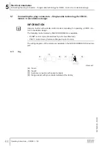
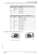
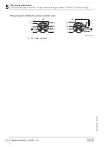
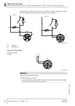
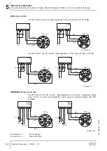
Connecting the motor and encoder system via KK terminal box
Operating Instructions – CM3C63 – 100
58
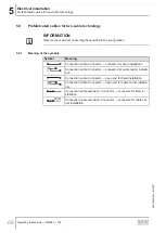
5.8.3
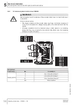
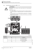
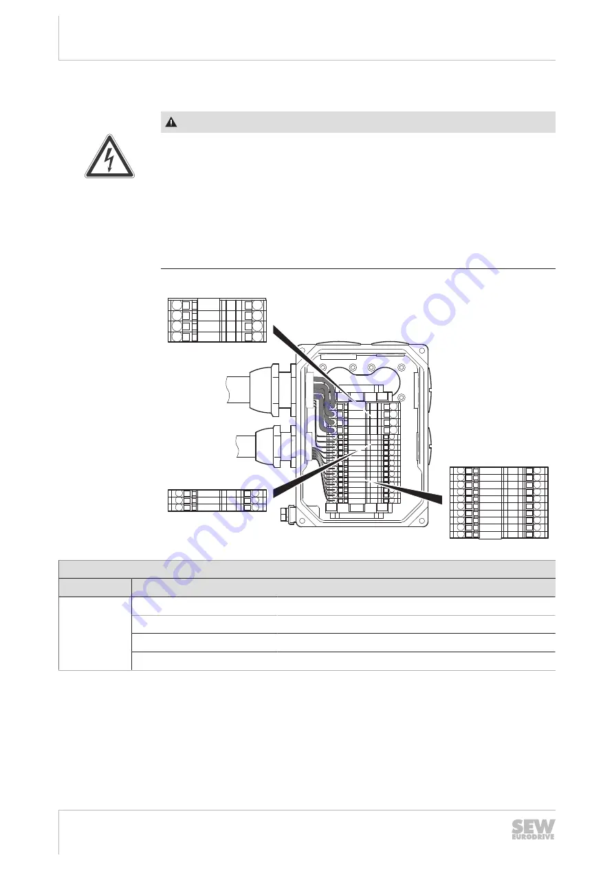
Terminal assignment terminal box CM3C63
WARNING
Risk of electric shock if conductors of the encoder cable come in contact with power
connections.
Fatal or serious injuries.
•
The single conductors of the encoder cable must have a minimum clearance of
4 mm to all uninsulated or voltage-carrying parts of the terminal board and the
eyelets.
•
All single conductors must be insulated using a cable jacket or an insulating
tubing until they are connected to the terminal strip. Make sure the insulating
tubing cannot get out of place.
PE
W
V
U
3a
4a
5a
10
9
8
7
6
5
4
3
2
1
PE
W
V
U
3a
4a
5a
10
9
8
7
6
5
4
3
2
1
[1]
[2]
[3]
30661741323
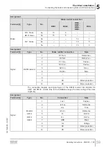
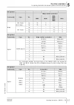
Assignment
Terminal [1]
No.
Connection
Supply system
U
Line connection phase U
V
Line connection phase V
W
Line connection phase W
PE
PE connection
26870460/EN – 05/2021

