5
Electrical installation
Assembling the cables
Operating Instructions – CM3C63 – 100
84
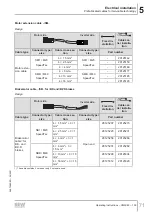
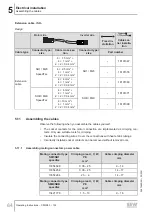
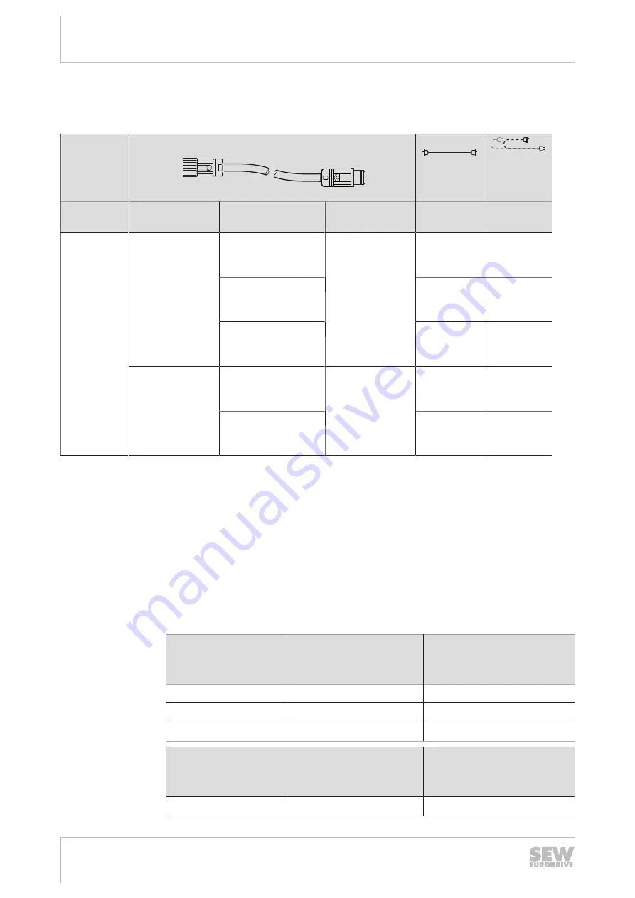
Extension cable ../SH..
Design
Motor side
Inverter side
Fixed in-
stallation
Cable car-
rier installa-
tion
Cable type
Connector type/
size
Cable cross sec-
tion
Connector type/
size
Part number
Extension
cable
SH1 / M23
SpeedTec
4 × 1.5 mm
2
+
4 × 1 mm
2
+
2 × 2 × 0.34 mm
2
SH1 / M23
–
18191347
4 × 2.5 mm
2
+
4 × 1 mm
2
+
2 × 2 × 0.34 mm
2
–
18191355
4 × 4 mm
2
+
4 × 1 mm
2
+
2 × 2 × 0.34 mm
2
–
18191363
SHB / M40
SpeedTec
4 × 6 mm
2
+
4 × 1 mm
2
+
2 × 2 × 0.34 mm
2
SHB / M40
–
18191371
4 × 10 mm
2
+
4 × 1 mm
2
+
2 × 2 × 0.34 mm
2
–
18191398
5.11
Assembling the cables
Observe the following when you assemble the cables yourself:
•
The socket contacts for the motor connection are implemented as crimping con-
tacts. Only use suitable tools for crimping.
•
Insulate the connecting wires. Cover the connections with heat shrink tubings.
•
Incorrectly installed socket contacts can be removed without removal tools.
5.11.1
Assembling mating connectors power cable
Mating connector type
SM1/SB1
speedtec
Crimping area U, V, W,
PE
mm
2
Cable crimping diameter
mm
13354698
0.35 – 2.5
9 – 14
13354256
0.35 – 2.5
14 – 17
13354264
2.5 – 4
14 – 17
Mating connector type
SMB/SBB
speedtec
Crimping area U, V, W,
PE
mm
2
Cable crimping diameter
mm
13421778
1.5 – 10
9 – 16
26870460/EN – 05/2021


