5
Electrical installation
Options
Operating Instructions – CM3C63 – 100
86
5.12.3
Thermal motor protection
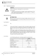
NOTICE
Motor overheating due to inadequate thermal motor protection.
Motor damage
•
In addition to a temperature sensor activate a current monitoring device (I
2
t, rms
current monitoring) and a motor model for thermal protection, as installed in
servo systems by SEW‑EURODRIVE.
/PK temperature sensor
INFORMATION
Make sure the used inverter has the relevant evaluation electronics for the PK
(PT1000) temperature sensor. The thermal protection function must become active in
case of overtemperature.
Type designation
/PK
Description
Thermal motor protection in combination with the corresponding evaluation electronics
prevents the motor from overheating and consequently from being damaged. A tem-
perature sensor provides only indirect protection as only one sensor value is deter-
mined.
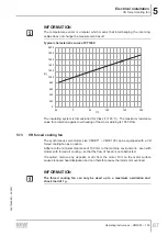
The /PK option consists of a PT1000 platinum sensor, which is installed in one of the 3
motor windings. Unlike the /KY semiconductor sensor, the platinum sensor has an al-
most linear characteristic curve and is more accurate. In combination with a frequency
inverter containing the thermal model of the motor, the frequency inverter can also
provide a motor protection function because of the /PK.
The option /PK equals a protective separation.
Technical data
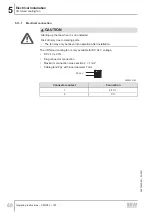
The PT1000 temperature sensor continuously detects the motor temperature.
PT1000
Connection
Black – red
Total resistance at 20 – 25 °C
1050 Ω < R < 1150 Ω
Operating range V
eff
25 V
Test current
< 3 mA
Overvoltage category
3
Degree of pollution
1
Maximum installation altitude
5000 m NHN
26870460/EN – 05/2021

