background image

6

Startup

Parameter description

Operating Instructions – CMP ELVCD

64

Parameter 080.4

Signal: SINCOS-track signals fault

The parameter indicates whether

the track signals of the sine-cosine encoder are not present

or the encoder is configured incorrectly.

Parameter 080.5

Signal: Resolver track signals or carrier failure fault

The parameter indicates whether

the track signals of the resolver are present

or the encoder is configured incorrectly.

Parameter 080.6

Signal: 5 V electronics supply fault

The parameter indicates whether the 5 V electronics supply failed.

Parameter 080.7

Signal: 12 V electronics supply fault

The parameter indicates whether the 12 V electronics supply failed.

Parameter 080.8

Signal: 24 V logic supply fault

The parameter indicates whether the 24 V logic supply failed.

Parameter 080.9

Signal: Current measurement offset fault

The  parameter  indicates  an  offset  fault  during  current  measurement.  Contact
SEW‑EURODRIVE Service.

Parameter 081.0

Signal: DC link/output stage overcurrent fault

The parameter indicates a defect in the winding or the output stage.

Parameter 081.1

Signal: DC link undervoltage

The parameter indicates whether

the power supply is not present

or whether the value is set too high.

Parameter 081.2

Signal: DC link overvoltage

The parameter indicates whether the DC link voltage is > 70 V.

22759468/EN – 11/2017

Summary of Contents for CMP ELVCD

Page 1: ...22759468_1117 Drive Technology Drive Automation System Integration Services Operating Instructions Decentralized Extra Low Voltage Servo Drive CMP ELVCD Edition 11 2017 22759468 EN...

Page 2: ...SEW EURODRIVE Driving the world...

Page 3: ...ive separation 11 2 10 Startup operation 11 3 Device structure 12 3 1 Overview 12 3 2 ELVCD inverter integrated 12 3 3 ELVCD inverter mounted close to the motor 14 3 4 ELVCD inverter 15 3 5 Nameplate...

Page 4: ...MultiMotion 84 8 3 Function block error messages 84 8 4 Fault list 85 8 5 Resetting fault messages 88 8 6 Unit replacement 88 8 7 Electronics Service by SEW EURODRIVE 89 8 8 Shutdown 89 8 9 Storage 8...

Page 5: ...ew eurodrive com provides a wide selection of documents for download in various languages If required you can also order prin ted and bound copies of the documentation from SEW EURODRIVE 1 3 Structure...

Page 6: ...directly integrated into the instructions just before the de scription of the dangerous action This is the formal structure of an embedded safety note SIGNAL WORD Type and source of hazard Possible c...

Page 7: ...contained in this documentation to achieve the specified product characteristics and performance features SEW EURODRIVE as sumes no liability for injury to persons or damage to equipment or property r...

Page 8: ...roduct pay attention to the following regula tions conditions documentation and information National and regional safety and accident prevention regulations Warning and safety signs on the product All...

Page 9: ...n in electrical plants or machines In case of installation in electrical systems or machines startup of the product is pro hibited until it is determined that the machine meets the requirements stipul...

Page 10: ...up to 4000 m asl under the fol lowing conditions Taking the reduced continuous rated current into consideration see chapter Technical data of the documentation Above 2000 m asl the air and creeping d...

Page 11: ...r rotating parts as well as hot surfaces during operation Additional preventive measures may be required for applications with increased haz ard potential You have to check the protection devices afte...

Page 12: ...of the following components ELVCD inverter integrated 2 12 or mounted close to the motor 2 14 Servomotor CMP ELVCD Gear unit option Information about the CMP servomotors and the gear units can be foun...

Page 13: ...the following power plug positions Power plug position 1 KKL1 Power plug position 3 default KKL3 20901941643 3 2 2 Inverter positions The ELVCD drive is available with the following ELVCD inverter pos...

Page 14: ...ows an ELVCD drive with ELVCD inverter mounted close to the motor 1 2 2 3 20428917003 1 ELVCD inverter 2 Nameplate 3 CMP ELVCD servomotor optionally with gear unit 3 3 1 Power plug positions The ELVCD...

Page 15: ...L R 0 Standard position 20786001547 The following figure shows an example of the differently aligned motor plugs 2897468043 The alignment of the plug connectors can be changed if necessary 3 4 ELVCD...

Page 16: ...ODRIVE may perform repairs 3 5 Nameplate The nameplate can be found on the motor and the side of the inverter The following figure gives an example of a nameplate of an ELVCD drive with helical bevel...

Page 17: ...sible Number Safety related component 01 ELVCD inverter 04 Encoder 07 ELVCD inverter and encoder 3 6 Type designation The following table shows an example of the type designation of the KA37 CMP50S BK...

Page 18: ...ts up unintentionally Severe or fatal injuries Secure the output shaft against rotation 4 2 Required tools and resources Set of wrenches Torque wrench Mounting device Compensation elements shims and s...

Page 19: ...and sealing rings this could damage the material Align the motor carefully to avoid placing any unacceptable strain on the motor shafts Observe the permitted overhung and axial loads specified in the...

Page 20: ...4 5 3 Installation in damp locations or outdoors ELVCD drives are supplied in corrosion resistant design for use in damp areas or in the open Repair damage to the paint work Condensation is not permit...

Page 21: ...4 6 Mounting close to the motor The following figure shows the mounting dimensions for mounting the ELVCD inverter close to the motor 149 M6 M6 17823801739 For installation use 2 M6 screws preferably...

Page 22: ...that low impedance HF capable equipotential bonding is provided see also EN 60204 1 or DIN VDE 0100 540 Between the ELVCD drive and the mounting rail provide for a connection over a wide area To do s...

Page 23: ...r supply unit and the ELVCD drive must not exceed 10 m with a core cross section of 2 5 mm2 If longer cables are required contact SEW EURODRIVE If you connect more than one ELVCD drive to one power su...

Page 24: ...D ELVCD MOVI PLC CAN 9 1 2 2 5 7 8 6 F11 3 F12 DHP11B X30 2 2 2 2 0 1 2 K11 GND DC 24 V DC 48 V K12 4 18014410730672779 1 Higher level controller 2 Supply system 3 F11 F12 Fuse 4 K11 K12 Line contacto...

Page 25: ...it switch CW positive 3 Limit switch CCW negative The ELVCD drive can evaluate 9 digital inputs 2 of which are for limit switches and forward these signals to the higher level controller via the CAN b...

Page 26: ...ft of the ELVCD drive Determine the maximum power demand observing the efficiency A power supply with a nominal output of 500 W makes operation below the S1 charac teristic curve possible 40 C see cha...

Page 27: ...electrical installation see chapter Install ation topology example 2 24 Please pay attention to the following information when setting the switching thresholds of the external brake chopper The switch...

Page 28: ...tor 120 CAN terminating resistor Part number 13287036 Connection M12 63050395932099851 5 6 2 Connection cables The following table provides an overview of the cables available for this connection Cabl...

Page 29: ...ck 1 3 CAN_H White 2 x 1 CAN_L Blue 3 x 2 The CAN 2 system bus is galvanically isolated The ELVCD drive should prefer ably be connected to the CAN 2 X32 interface The CAN 1 system bus is not galvanica...

Page 30: ...X401 X5 X402 1 2 2 X401 X5 X402 9007220089443467 1 Equipotential bonding 2 22 2 Cable bushing of the motor and encoder cables only for mounting close to the motor X1 DC 24 V input DC 48 V input and di...

Page 31: ...Prefabricated cables for connecting SEW EURODRIVE components can be ordered For each connection the available prefabricated cables are listed Specify the part number and length of the required cable...

Page 32: ...t n 0 clockwise rotation 3 DI05 Digital input DI05 no function transparent 4 DI03 Digital input DI03 no function transparent 5 DI09 Digital input DI09 switch on output stage 6 DI07 Digital input DI07...

Page 33: ...A 1 2 No Name Function 1 GND Reference potential for DC link and electronics 2 DC link DC 48 V voltage supply for DC link INFORMATION In order to enable the output stage pin A5 and pin B8 must be jum...

Page 34: ...h 9 13 mm 9 1 rubber seal multiple leadthrough 1 x 6 mm 2 x 9 mm 10 1 locking bolt 6 mm 11 2 locking bolts 9 mm 12 1 rubber seal single leadthrough 11 5 15 5 mm INFORMATION Use one of the two pressure...

Page 35: ...ion about this connection Function Motor connection Connection type Cable with plug connector M23 8 pin female type BSTA 078 Connection image D A 3 1 C B 2 4 No Name Function 1 U Motor phase U output...

Page 36: ...plug connector M23 12 pin female 0 coded Connection image 9 1 2 7 6 5 11 12 3 4 8 10 No Name Function 1 R1 Signal input reference 2 R2 Signal input reference 3 S1 Signal input cosine 4 S3 Signal inpu...

Page 37: ...ble with plug connector M23 12 pin female 0 coded Connection image 9 1 2 7 6 5 11 12 3 4 8 10 No Name Function 1 n c Not connected 2 n c Not connected 3 S1 Signal input cosine 4 S3 Signal input cosine...

Page 38: ...ly if the device will not perform any safety functions ac cording to EN ISO 13849 1 INFORMATION Use only shielded cables for this connection Function Input for safe disconnection Connection type M12 5...

Page 39: ...pliant These cables ensure that there is a continu ous connection to the housing of the device The following table shows information about this connection Function CAN interface input Connection type...

Page 40: ...nnected to the connector housing in a way that is EMC compliant These cables ensure that there is a continu ous connection to the housing of the device The following table shows information about this...

Page 41: ...l connections Operating Instructions CMP ELVCD 41 5 8 10 X5 Diagnostic interface INFORMATION Diagnostic interface X5 may only be used by SEW EURODRIVE Service Never remove the screw plug from diagnost...

Page 42: ...ll the protection devices according to the regulations Check the protection devices on a regular basis Let the device and the connected options cool down before you start working on them WARNING Risk...

Page 43: ...re switching off NOTICE Danger due to faulty referencing after a voltage supply failure If the travel range of the system is greater than the multi turn range of the absolute encoder 4096 motor revolu...

Page 44: ...oller The specified technology points correspond with the minimum requirement The MOVITOOLS MotionStudio engineering software must be installed on the en gineering PC Version V180 100 or higher of the...

Page 45: ...Access with MOVITOOLS MotionStudio always has to take place via the ELVCD DriveManager plug in 1 Select connection type Ethernet under Select connection mode and create net work 2 Make sure that you a...

Page 46: ...ORMATION This chapter describes the startup of the ELVCD drive using the MultiMotion program module of the MOVITOOLS MotionStudio software Refer to the MultiMotion manual for further information on th...

Page 47: ...PLC Editor 6 To set the Task configuration switch to the Resources tab 7 In the TaskPriority folder set the TaskPriority cycle time to a value of 10 ms 8 Add MC_CommunicationTask_CAN to the last line...

Page 48: ...apter 1 Right click on the controller in the project The context menu is displayed 2 Click on menu command ELVCD DriveManager The ELVCD DriveManager is opened with a list of previously configured ELVC...

Page 49: ...the Homing operating mode New actual position zero 12539348491 6 6 6 Fixed stop positive Reference travel takes place by approaching the stop in positive direction New actual position offset NOTICE D...

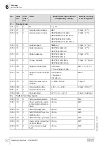
Page 50: ...2770 0 Actual velocity 231 1 0 231 1 user units 003 0 32771 0 Actual position 231 1 0 231 1 increments 004 0 32772 0 Actual position 231 1 0 231 1 user units 005 0 32773 0 Active current 0 400 IN Moto...

Page 51: ...ve Bit 2 033 0 32817 0 Digital input DI03 Inactive Active Bit 3 034 0 32817 0 Digital input DI04 Inactive Active Bit 4 035 0 32817 0 Digital input DI05 Inactive Active Bit 5 036 0 32817 0 Digital inpu...

Page 52: ...Digit 2 12 Nm A 077 0 161 0 Angular encoder type 0 Resolver 1 Sine cosine encoder Bit 12 13 14 15 077 1 170 0 Angular encoder configur ation 0 Single turn 1 Reserved 2 Multi turn Bit 0 1 077 2 171 0...

Page 53: ...1 6 112 0 I2 t_at_80 Yes no Bit 25 081 7 112 0 Temperature motor 5 C below maximum Yes no Bit 26 081 8 112 0 Temperature_output stage_5 C_below_maxi mum Yes no Bit 27 081 9 112 0 Lag error monitoring...

Page 54: ...0001 ms No Index dec Sub index dec Name MOVITOOLS MotionStudio range factory setting CANopen scaling or bit assignment 2__ Control parameter 20_ Speed control 200 0 235 0 Speed controller configurati...

Page 55: ...48 0 Direction of rotation reversal 0 No direction of rota tion not reversed 1 Yes direction of rota tion is reversed Bit 10 No Index dec Sub index dec Name MOVITOOLS MotionStudio range factory settin...

Page 56: ...utputs deactiv ated 2 4 Reserved 5 Digital outputs acti vated Bits 7 8 9 No Index dec Sub index dec Name MOVITOOLS MotionStudio range factory setting CANopen scaling or bit assignment 7__ Control func...

Page 57: ...ng 2 Rapid stop 3 Immediate stop Bit 2 831 0 114 116 0 Undertemperature overtemper ature of the power electronics 0 No response 1 Display warning 2 Rapid stop 3 Immediate stop Bit 3 832 0 114 116 0 DC...

Page 58: ...p Bit 30 840 0 115 117 0 CAN communication error 0 No response 1 Display warning 2 Rapid stop 3 Immediate stop Bit 22 88_ SBus communication 886 0 320 0 CAN address 0 63 887 0 324 0 CAN active 0 No 1...

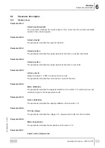
Page 59: ...signed position of the drive in user units Parameter 005 0 Active current Range of values 0 400 of nominal motor current The parameter indicates the current active current of the drive Parameter 006...

Page 60: ...rning status The parameter indicates whether a warning is active Parameter 020 0 Normal state The parameter indicates whether the drive is in a normal operating state Parameter 021 0 STO safe state re...

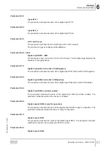
Page 61: ...ates the state of the digital input DI07 limit switch CCW negative Parameter 038 0 Digital input DI08 limit switch CW positive The parameter indicates the state of the digital input DI08 limit switch...

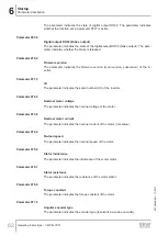
Page 62: ...ndicates the serial number ID of the inverter Parameter 072 0 Nominal motor voltage The parameter indicates the nominal voltage of the motor Parameter 073 0 Nominal motor current The parameter indicat...

Page 63: ...e number of pole pairs of the motor Parameter 079 0 Encoder offset The parameter indicates the encoder offset in increments Parameter 080 0 Signal Motor overtemperature The parameter indicates whether...

Page 64: ...080 7 Signal 12 V electronics supply fault The parameter indicates whether the 12 V electronics supply failed Parameter 080 8 Signal 24 V logic supply fault The parameter indicates whether the 24 V l...

Page 65: ...ontroller pro tection model has reached 80 Parameter 081 7 Signal Motor temperature 5 C below maximum The parameter indicates whether the motor temperature reached the threshold of 5 C below the permi...

Page 66: ...6 Signal CAN communication error The parameter indicates whether the CAN bus communication failed Check whether CAN bus addresses have been assigned twice Parameter 082 7 Signal RS232 communication er...

Page 67: ...is triggered in the event of a rapid stop Parameter 137 0 Limit switch delay MultiMotion The parameter defines the limit switch delay of the drive which is triggered in the event of a collision with t...

Page 68: ...ition controller dead zone position difference This parameter defines the area where the position controller is not active Parameter 290 0 Current controller gain This parameter defines the gain facto...

Page 69: ...2 0 defines whether digital input DI02 is active Parameter P603 0 defines whether digital input DI03 is active If the digital input is active the status of the digital input can undergo further pro ce...

Page 70: ...standard KTY temperature sensor from SEW EURODRIVE Parameter 805 1 KTY temperature sensor switch off threshold This parameter defines the maximum permissible motor temperature If the measured motor te...

Page 71: ...ler fault I2 t at 100 1 Display warning Bit 19 P835 0 I2 t at 80 1 Display warning Bit 25 P836 0 Motor temperature 5 C below maximum limit 3 Immediate stop Bit 26 P837 0 Output stage tempera ture 5 C...

Page 72: ...meter 907 0 Move to zero position after reference travel The parameter defines whether the drive moves to the zero position after the refer ence travel Parameter 923 0 Lag error window MultiMotion Thi...

Page 73: ...ng homing the command Save parameter is executed as well If homing is interrupted without the message Homing Done the drive signals Ready for operation but without the InGear message To switch back to...

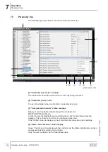
Page 74: ...D drives can be found in the folder User Data of the current project in MOVITOOLS MotionStudio Gray No parameter set present 6 IP address display Display of IP address of controller in MOVITOOLS Motio...

Page 75: ...MotionStudio After successfully backing up the Backed up parameters status display appears in green 12 Load parameter set button This button is used to open the dialog window for loading a parameter...

Page 76: ...mmunication status status message Display of communication status between the controller and MOVITOOLS MotionStudio In order to execute diagnostic and control functions the Online status must be signa...

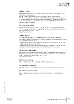
Page 77: ...itches back to the overview window of the ELVCDDriveManager If you have changed a parameter you have the choice between permanent and tem porary retention of the changes Click on the Yes button to sto...

Page 78: ...imum delay defined in the axis configuration are not effective in manual mode Damage to the drive or the system Ensure that you do not exceed the permissible limit values for setpoint speed and ramps...

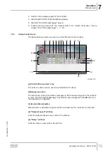
Page 79: ...4 5 6 7 8 9 10 11 16 B 1 A 21010803211 A All ELVCD inverters area The buttons in this area are used on all listed ELVCD drives B Single axes area The edit boxes buttons and status messages in this ar...

Page 80: ...All active faults with the exception of certain STO fault messages are acknowledged by pressing this button These can only be acknowledged by restarting the drive If the enable and setpoints 0 are sti...

Page 81: ...OOLS MotionStudio In order to execute diagnostic and control functions the Online status must be signaled This is shown in the form of a continuous green bar If the Offline status is displayed check t...

Page 82: ...ating Instructions CMP ELVCD 82 Code Operating status Meaning 6 FAULT A fault occurred The motor is de energized 17 STO_SAFESTOP STO has been activated The inverter safely switches off the motor torqu...

Page 83: ...nge connection with gearmo tors only Internal seal defective Contact SEW EURODRIVE Service Have SEW EURODRIVE Service change the internal seal 8 1 2 Brake malfunctions Fault Possible cause Measure Bra...

Page 84: ...been re placed or the order of the axis configuration has changed The referenced signal has been lost Perform another reference travel 16461826 E_ELVCD_PARA METER_CON FIG_CHANGED The parameter set ha...

Page 85: ...5 Sine cosine R2485 commu nication error The angular encoder is de fective or an incorrect an gular encoder was selec ted Contact SEW EURODRIVE Service 7 29584 Sine cosine en coder track signal error...

Page 86: ...vice 19 8978 I t error motor I t at 100 I t monitoring has tripped Incorrect nominal current setting Check and correct the nominal motor current setting 20 8977 I t error controller I t at 100 I t mon...

Page 87: ...tion of the limit switches If there are no limit switches connected set the limit switch type to NO contact Check the wiring 35 24985 Rapid stop timeout The rapid stop ramp was not executed correctly...

Page 88: ...Stack overflow Internal fault Contact SEW EURODRIVE Service 63 21889 Checksum error Internal fault Contact SEW EURODRIVE Service 64 24967 Fault during ini tialization Internal fault Contact SEW EUROD...

Page 89: ...on the status display Nature of the fault Accompanying circumstances Unusual events preceding the problem 8 8 Shutdown To shut down the ELVCD drive de energize the drive using appropriate measures 8 9...

Page 90: ...ste disposal Observe the applicable national regulations Dispose of materials separately in ac cordance with the nature of the materials and the regulations in force for example Electronics scrap circ...

Page 91: ...y NOTICE Damage to the drive Potential damage to property Note that only SEW EURODRIVE Service or specialists trained by SEW EURODRIVE are allowed to carry out motor and or brake maintenance 9 1 Clean...

Page 92: ...e high degree of UV exposure low ambient temperatures 9 3 1 Motor The following table shows the inspection intervals for the motor Time interval Activity Design Every 3000 hours of operation at least...

Page 93: ...it is used as a holding brake with braking work with emergency off switching this inspection must be carried out every 3000 operating hours and no later than after 2 years If braking work of 1000 kJ...

Page 94: ...heat sink 400 W The braking resistor goes to high resistance in case of over load Nominal input current INInverter 6 2 A 8 3 A 8 5 A 12 5 A Maximum input current INmax 32 A for 2 s Output frequency f...

Page 95: ...ction accord ing to EN 60529 IP65 Housing closed and all plug connectors inserted or sealed with protection caps Operating mode according to EN 60034 1 S1 S3 Type of cooling Natural cooling to DIN 417...

Page 96: ...S301 DS402 Baud rate 500 kBaud Address Automatic according to DS305 address assignment according to serial number can be set via MultiMotion configuration Number of drives that can be addressed 8 If y...

Page 97: ...7 CMP50M ELVCD and ELVCD DC I M M n M DC 2 35686 10 7 23949 10 2 36917 10 12 1 2 3 10 5 2 Torque current characteristic curve for CMP50S ELVCD and CMP50S ELVCD EC M Nm I A M f I Mot 0 0 5 1 0 1 5 2 0...

Page 98: ...P50M ELVCD and CMP50M ELVCD EC M Nm I A M f I Mot 0 0 5 1 0 1 5 2 0 2 5 3 0 3 5 4 0 4 5 0 5 10 15 20 25 30 35 18014411017118475 10 5 4 Dynamic characteristic curve CMP50S ELVCD and CMP50S ELVCD EC M N...

Page 99: ...n inverter 0 W 0 75 Nm 0 80 Nm 0 80 Nm 7 5 W 0 63 Nm 0 70 Nm 0 70 Nm 15 W 0 63 Nm 0 45 Nm 0 45 Nm Mounting close to the motor 0 W 0 95 Nm 1 05 Nm 1 05 Nm 7 5 W 0 95 Nm 1 00 Nm 1 00 Nm 15 W 0 95 Nm 1 0...

Page 100: ...of CMP50S ELVCD P W 0 0 1 0 2 0 3 0 4 0 5 0 6 0 7 0 8 0 9 1 0 1 1 0 5 10 15 20 25 M Nm 17437928203 P Average chopper power loss Thermal capacity utilization of CMP50M ELVCD P W 0 0 1 0 2 0 3 0 4 0 5...

Page 101: ...P W 0 0 1 0 2 0 3 0 4 0 5 0 6 0 7 0 8 0 9 1 0 1 1 0 10 20 30 40 50 M Nm 17493675275 P Average chopper power loss Thermal capacity utilization of CMP50M ELVCD EC mounting close to the motor P W 0 0 1...

Page 102: ...e times of switching elements or controllers were not taken into ac count INFORMATION If the permitted braking work per braking W1 is exceeded during braking or if the per mitted total braking work Wi...

Page 103: ...total braking work Winsp is reached it can no longer be guaranteed that the brake will be applied In this case the drive does not brake 10 7 CAN connection cables When individual CAN connection cable...

Page 104: ...10 7 4 Electrical properties in total Electrical properties in total Characteristic rated impedance Impedance ohms 120 Nominal capacitance conductor conductor Capacitance pF ft 12 8 Nominal capacitanc...

Page 105: ...10 Technical data CAN connection cables Operating Instructions CMP ELVCD 105 Electrical properties in total Max recommended amperage Amperage 2 1 A per conductor at 25 C 22759468 EN 11 2017...

Page 106: ...gs 10 8 1 Dimension drawing of CMP50S ELVCD 08 472 00 14 CMP50S ELVCD RH1M KKL 3 114 85 2 5 8 60j6 11k6 23 150 5 173 5 87 5 213 15 86 19 4 22 75 5 5 AK0H KKL 3 150 5 49 5 38 4 12 5 DIN 332 DR M4 11k6...

Page 107: ...drawing of CMP50S BK BP ELVCD CMP50S BK BP ELVCD 08 470 00 14 114 85 2 5 8 60j6 11k6 23 179 202 87 5 213 15 86 19 4 22 RH1M KKL 3 DIN 332 DR M4 DIN 332 DR M4 3 5 11k6 23 16 4 12 5 AK0H KKL 3 49 5 38 1...

Page 108: ...mension drawing of CMP50M ELVCD CMP50M ELVCD 08 473 00 14 RH1M KKL 3 114 85 2 5 60j6 11k6 23 213 15 86 8 189 5 212 5 87 5 19 4 22 75 5 5 AK0H KKL 3 DIN 332 DR M4 16 23 3 5 11k6 4 12 5 49 5 38 189 5 RH...

Page 109: ...on drawing of CMP50M BK BP ELVCD 08 471 00 14 CMP50M BK BP ELVCD RH1M KKL 3 114 85 2 5 60j6 11k6 8 23 218 241 213 15 86 87 5 19 4 22 75 5 5 75 5 5 AK0K KKL 3 16 23 3 5 11k6 DIN 332 DR M4 4 12 5 49 5 3...

Page 110: ...8 5 Dimension drawing of CMP50S ELVCD EC 16 23 3 5 4 11k6 12 5 DIN 332 DR M4 CMP50S ELVCD EC SB1 RH1M AK0H AK1H EK1H KK 08 811 00 16 26 5 15 85 5 8 2 5 60j6 11k6 40 5 17 5 150 5 173 5 23 30 75 5 5 15...

Page 111: ...6 Dimension drawing of CMP50S BK BP ELVCD EC 16 23 3 5 4 11k6 12 5 DIN 332 DR M4 CMP50S BK BP ELVCD EC SB1 RH1M 08 812 00 16 26 5 15 85 5 8 2 5 60j6 11k6 40 5 17 5 179 202 23 30 75 5 5 6 5 179 131 168...

Page 112: ...8 7 Dimension drawing of CMP50M ELVCD EC 16 23 3 5 4 11k6 12 5 DIN 332 DR M4 CMP50M ELVCD EC SB1 RH1M 08 813 00 16 26 5 15 85 5 8 2 5 60j6 11k6 40 5 17 5 189 5 212 5 23 30 75 5 5 149 189 5 131 168 11...

Page 113: ...8 Dimension drawing of CMP50M BK BP ELVCD EC 16 23 3 5 4 11k6 12 5 DIN 332 DR M4 CMP50M BK BP ELVCD EC SB1 RH1M 08 814 00 16 26 5 15 85 5 8 2 5 60j6 11k6 40 5 17 5 218 241 23 30 75 5 5 218 131 168 110...

Page 114: ...piling the technical documents Place Date 19 07 2017 Managing Director Technology Johann Soder a b decentralized extra low voltage servo drives CMP ELVCD in accordance with EMC Directive 2014 30 EU 4...

Page 115: ...Tel 88 01729 097309 salesdhaka seweurodrivebangladesh com Belarus Sales Minsk Foreign unitary production enterprise SEW EURODRIVE RybalkoStr 26 220033 Minsk Tel 375 17 298 47 56 298 47 58 Fax 375 17 2...

Page 116: ...12 Fax 86 22 25323273 http www sew eurodrive cn info sew eurodrive cn Assembly Sales Service Suzhou SEW EURODRIVE Suzhou Co Ltd 333 Suhong Middle Road Suzhou Industrial Park Jiangsu Province 215021 Te...

Page 117: ...http www copam egypt com copam copam egypt com Estonia Sales Tallin ALAS KUUL AS Reti tee 4 75301 Peetri k la Rae vald Harjumaa Tel 372 6593230 Fax 372 6593231 http www alas kuul ee veiko soots alas k...

Page 118: ...URODRIVE GmbH Co KG Ernst Blickle Stra e 1 76676 Graben Neudorf Tel 49 7251 75 1710 Fax 49 7251 75 1711 scc mechanik sew eurodrive de Electronics SEW EURODRIVE GmbH Co KG Ernst Blickle Stra e 42 76646...

Page 119: ...ODRIVE India Private Limited Plot No 4 GIDC POR Ramangamdi Vadodara 391 243 Gujarat Tel 91 265 3045200 Fax 91 265 3045300 http www seweurodriveindia com salesvadodara seweurodriveindia com Assembly Sa...

Page 120: ...Coast Rue des P cheurs Zone 3 26 BP 916 Abidjan 26 Tel 225 21 21 81 05 Fax 225 21 25 30 47 info sew eurodrive ci http www sew eurodrive ci Japan Assembly Sales Service Iwata SEW EURODRIVE JAPAN CO LTD...

Page 121: ...l Qu retaro C P 76220 Quer taro M xico Tel 52 442 1030 300 Fax 52 442 1030 301 http www sew eurodrive com mx scmexico seweurodrive com mx Sales Service Puebla SEW EURODRIVE MEXICO S A de C V Calzada Z...

Page 122: ...Fernando de la Mora Barrio Bernardino Tel 595 991 519695 Fax 595 21 3285539 sewpy sew eurodrive com py Peru Assembly Sales Service Lima SEW EURODRIVE DEL PERU S A C Los Calderos 120 124 Urbanizacion I...

Page 123: ...e Celje Pakman Pogonska Tehnika d o o UI XIV divizije 14 3000 Celje Tel 386 3 490 83 20 Fax 386 3 490 83 21 pakman siol net South Africa Assembly Sales Service Johannesburg SEW EURODRIVE PROPRIETARY L...

Page 124: ...info imhof sew ch Taiwan Sales Taipei Ting Shou Trading Co Ltd 6F 3 No 267 Sec 2 Tung Huw S Road Taipei Tel 886 2 27383535 Fax 886 2 27368268 Telex 27 245 sewtwn ms63 hinet net http www tingshou com...

Page 125: ...ve com Southwest Region SEW EURODRIVE INC 3950 Platinum Way Dallas Texas 75237 Tel 1 214 330 4824 Fax 1 214 330 4724 csdallas seweurodrive com Western Region SEW EURODRIVE INC 30599 San Antonio St Hay...

Page 126: ...tion 20 Configuring digital output DO01 P620 0 69 Configuring digital output DO02 P621 0 69 Connection Display 31 EMC aspects 22 Installation instructions 23 Installation topology 24 Safety notes 10 C...

Page 127: ...Inspection intervals 92 Installation Close to motor 21 Close to the motor 21 Installing the ELVCD drive 19 Installation electrical DC 24 V DC 24 V 23 EMC aspects 22 EMC compliant installation 22 Equip...

Page 128: ...tive separation 11 R Rapid stop delay SINCOS P136 0 67 Reference travel fault P082 2 65 Repair 89 Required tools and resources 18 Reset 88 Response delay lag error P925 0 72 Restrictions to applicatio...

Page 129: ...on 9 Travel program invalid jump destination P082 5 66 Travel program unknown fault P082 4 66 Type designation 17 U UL compliant installation 23 Undervoltage threshold value P806 0 70 Unit structure N...

Page 130: ......

Page 131: ......

Page 132: ...SEW EURODRIVE Driving the world SEW EURODRIVE GmbH Co KG Ernst Blickle Str 42 76646 BRUCHSAL GERMANY Tel 49 7251 75 0 Fax 49 7251 75 1970 sew sew eurodrive com www sew eurodrive com...

Reviews: