


4
8
Gear Units for Trolley Drive Systems - Operating Instructions
Required tools
4
Assembly / Disassembly
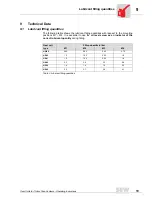
4.1
Required tools
•
Wrench set
•
Mounting device
•
Shims and distance rings, if necessary
•
Fixing devices for input and output elements
•
Lubricant (e.g. NOCO
®
fluid)
Installation
tolerances
4.2
Installing the drive rod
Install the supplied drive rod (with Spiroplan
®
gear unit HW30 and helical-worm gear unit
HS40/41) into the operating lever and secure it with a lock nut.
4.3
Gear units with solid shafts
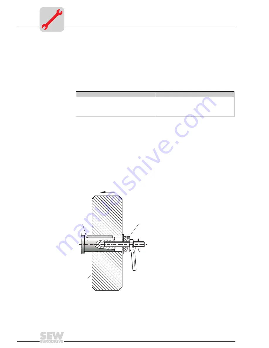
Mounting of
carrying wheels
Figure 1 shows an example of a mounting device for the installation of a carrying wheel
onto the gear unit or motor shaft ends. It may be possible to dispense with the thrust
bearing on the mounting device.
03605AXX
Figure 1: Example of a mounting device for installation of carrying wheels
Shaft end
Flanges
Diametric tolerances in accordance with DIN 748
•
ISO k6 for solid shafts with d, d
1
≤
50 mm
•
ISO k6 for solid shafts with d, d
1
> 50 mm
•
Center hole in accordance with DIN 332,
shape DR..
Centering shoulder tolerances in accordance with
DIN 42948
•
ISO j6 with b
1
≤
230 mm
•
ISO h6 with b
1
> 230 mm
3
1
2
1 Shaft end of gear unit
2 Thrust bearing
3 Carrying wheel
Summary of Contents for HK40
Page 2: ...SEW EURODRIVE ...


