Gear Units for Trolley Drive Systems - Operating Instructions
9
4
Gear units with solid shafts
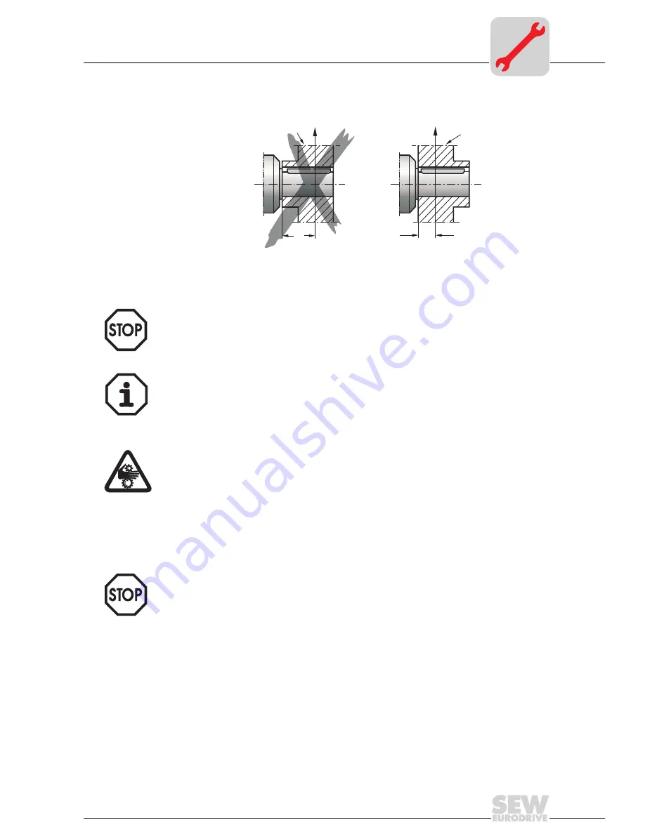
Figure 2 shows the correct mounting arrangement
b
of a carrying wheel in order to
avoid impermissible overhung loads.
03604AEN
Figure 2: Correct mounting arrangement of a carrying wheel
•
Only use a mounting device (see Figure 1) for installing input and output elements.
Use the center bore and the thread on the shaft end for positioning purposes.
•
Never drive carrying wheels, etc. onto the shaft end by hitting them with a
hammer (damage to bearings, housing and the shaft)!
•
Power transmission elements should be balanced after fitting and must not give rise
to any impermissible radial or axial forces (see Figure 2 / permitted values see the
"Trolley drive systems" catalog).
Note:
•
Assembly is easier if you first apply lubricant to the output element or heat it up
briefly (80 to 100 °C).
Input and output elements such as carrying wheels must have protection against
contact!
Mechanical
clutch
The output can be mechanically separated from a continuously running motor by
activating the clutch.
Pole-switchable motors or motors controlled by frequency inverters should be engaged
at low output speeds.
X
1
X
1
b
F
X1
F
X1
a
X
1
X
1
b
F
X1
F
X1
a
wheel hub
wheel hub
incorrect
correct
Summary of Contents for HK40
Page 2: ...SEW EURODRIVE ...


