Manual – IPOSplus®
107
9
Introduction
IPOSplus
®
and Synchronized Motion
9
IPOS
plus
®
and Synchronized Motion
9.1
Introduction
MOVIDRIVE
®
and MOVITRAC
®
B allow for master-slave operation.
Further, you can synchronize several MOVIDRIVE
®
units more exactly, for example, for
applications with the following functions:
• Mechanical axes run by several drives (for example, gantries, multiple column
hoists). Note: For more project planning information in this case, refer to the
"MOVIDIRVE
®
– Multi-Motor Drives" manual).
• Speed or position of a slave axis is derived from the position of a master axis
(electronic shaft, electronic cam).
MOVIDRIVE
®
offers preconfigured hardware and software functions for both applica-
tions that can be activated by the IPOS
plus®
user program. These are described in the
following sections.
9.2
Speed synchronization via master/slave function
Via parameters P750 and P751, you can activate a simple speed synchronization for
MOVIDRIVE
®
and MOVITRAC
®
B without an IPOS
plus®
program or a technology unit.
A typical application example is the synchronized operation of 2 conveyor belts. For
more information, refer to the system manual.
9.3
Synchronous operation with a DRS option card
The DRS11 synchronous operation card allows for multiple axes to be operated at a
synchronous angle in relation to one another or with an adjustable proportional relation-
ship (electronic gear). The system differentiates between master and slave drives. The
master drive, used for positioning one or more slave drives, can also be an incremental
encoder. The slave drive(s) follow(s) the specified master positions.
The basis for synchronous operation is the continual comparison between master and
slave positions. The system determines the difference of the route information between
master and slave and stores this value in the form of incremental encoder signals in an
internal difference counter that cannot be accessed by the user. Binary signals, such as
"DRS SLAVE IN POS", "DRS LAG ERROR", "DRS PREWARNING" and "MASTER
STANDSTILL" are set depending on the basis of this difference. This counter is evalu-
ated depending on the operating mode. In synchronous operation, the internal differ-
ence counter is used to correct any angular offset between the slave and master to 0.
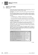
DRS is controlled using the variables H473, H476, H477 and H484 (see section "Over-
view of system variables"). The following section describes how the DRS can be ad-
dressed from the IPOS
plus®
program.
For more detailed information, refer to the "DRS11 Synchronous Operation Card" man-
ual.
INFORMATION
An IPOS
plus®
program is not required to use the synchronous operation card DRS11.
P
i
f
kVA
Hz
n
P
i
f
kVA
Hz
n

