5
Electrical installation
Installation instructions
Operating Instructions – MOVIGEAR
®
classic
54
5.3
Installation instructions
5.3.1
Thermal motor protection
NOTICE
Faulty installation.
Electromagnetic interference of the drives.
•
Install the connecting lead of the PK (PT1000) separately from other power
cables maintaining a distance of at least 200 mm. Laying together is only permit-
ted if either the cable of the PK (PT1000) or the power cable is shielded.
5.3.2
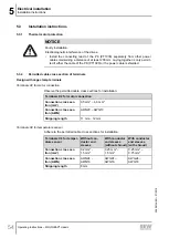
Permitted cable cross section of terminals
Design with cage clamp terminals
Terminals X2 for motor connection
Observe the permitted cable cross sections for installation:
Terminals X2 for motor connection
Connection cross sec-
tion (mm
2
)
0.5 mm
2
– 6.0 mm
2
Connection cross sec-
tion (AWG)
AWG20 – AWG10
Stripping length
11 mm – 12 mm
Terminals X4 for temperature sensor
Adhere to the permitted cable cross sections for installation:
Terminals X4 for temper-
ature sensor
Without con-
ductor end
sleeves
With conductor
end sleeves
(without shroud)
With conductor
end sleeves
(with shroud)
Connection cross sec-
tion (mm
2
)
0.2 mm
2
–
1.5 mm
2
0.25 mm
2
–
1.5 mm
2
0.25 mm
2
–
0.75 mm
2
Connection cross sec-
tion (AWG)
AWG24 –
AWG16
AWG24 –
AWG16
AWG24 –
AWG18
Stripping length
8 mm
25805134/EN – 07/2018
Summary of Contents for MGFAT1-DSM-C/PE
Page 2: ...SEW EURODRIVE Driving the world...
Page 123: ......

