5
Electrical installation
Installation topologies
Operating Instructions – MOVIGEAR
®
classic
58
5.4
Installation topologies
5.4.1
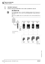
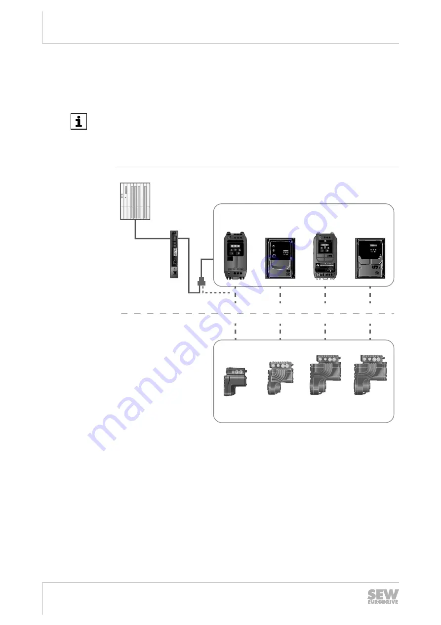
Installation topology with MOVITRAC
®
LTP-B, LTE-B+ and MOVI‑PLC
®
with CCU
INFORMATION
The following figure shows a schematic installation topology with the frequency in-
verter MOVITRAC
®
LTP-B, LTE-B+ and SEW‑EURODRIVE controller MOVI‑PLC
®
with CCU.
Observe the installation notes in the documentation of the inverter/controller that you
use.
2
2
2
2
2
2
2
X3
0
2
2
2
2
0
1
2
3
2
2
2
4
5
6
MOVITRAC
®
L
TP-B
L1/L L2/N L3
MOVITRAC
®
L
TP-B
U
V
W
1
3
5
7
9
11
2
4
6
8
10
L1/L
L2/N
L3
SBus
SEW
Controller
MOVI-PLC
®
/
Gateway
PLC
MOVITRAC
®
IP20
LTP-B
MOVITRAC
®
LTE-B+
IP20
MOVITRAC
®
LTE-B+
IP66
MOVITRAC
®
IP66
LTP-B
Field level
MGF..1-
DSM-C
MGF..2-
DSM
MGF..4-
DSM
MGF..4-
DSM/XT
Control cabinet level
Fieldbus
21493756555
25805134/EN – 07/2018
Summary of Contents for MGFAT1-DSM-C/PE
Page 2: ...SEW EURODRIVE Driving the world...
Page 123: ......

