Index
Index
A
Assembly
Safety notes ................................................... 10
B
Breather valve
Activate........................................................... 25
Mounting......................................................... 25
C
Cable cross section ............................................. 54
Cable entry, position............................................ 16
Cable glands ....................................................... 90
CE marking.......................................................... 81
Changing the mounting position .......................... 22
Changing the oil .................................................. 73
Changing the oil seal ........................................... 75
Cleaning .............................................................. 76
Coating ................................................................ 75
Connection
Installation instructions ................................... 54
Safety notes ................................................... 11
Terminal assignment ...................................... 60
Thermal motor protection ............................... 61
Connection box ................................................... 19
Connection cables, inspection and maintenance 76
Copyright notice .................................................... 7
Current carrying capacity of terminals/plug connect-
ors .................................................................. 82
Current, permitted ............................................... 86
D
Design notes ..................................................... 100
Device structure
Cable entry position........................................ 16
Housing mounting .......................................... 15
MGF..-DSM cover .......................................... 19
MOVIGEAR
®
classic drive unit ....................... 13
Nameplate and type designation of the drive unit
....................................................................... 18
Nameplate position......................................... 17
Diagnostics
Malfunctions of the mechanical drive ............. 64
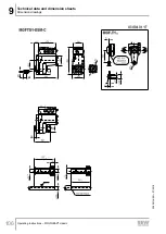
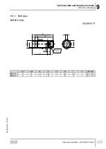
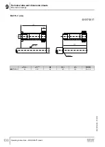
Dimension drawings .......................................... 104
MGF..1-DSM-C ............................................ 105
Notes ............................................................ 104
E
EAC ..................................................................... 81
Electrical connection ........................................... 11
Embedded safety notes......................................... 6
EMC cable glands
Overview ........................................................ 90
Equipotential bonding .......................................... 52
At the connection box (option)........................ 53
Extended storage ................................................ 66
F
Fluorocarbon rubber oil seal................................ 89
G
Gear unit venting ................................................. 24
H
Hazard symbols
Meaning............................................................ 6
Hollow shaft with keyway (MGFA..)............. 27, 100
Housing mounting ............................................... 15
Housing with threads (MGF.S) ....................... 15
Torque arm (MGF.T) ...................................... 15
I
Inspection ............................................................ 69
Connection cable............................................ 76
Inspection intervals......................................... 69
Preliminary work............................................. 72
Installation (electrical)
Cable cross section ........................................ 54
Equipotential bonding..................................... 52
Installation instructions ................................... 54
PE connection ................................................ 57
Terminal activation ................................... 55, 56
Terminal assignment ...................................... 60
Thermal motor protection ......................... 54, 61
Installation (mechanical)
Installation notes ............................................ 20
Installing the protective cover......................... 46
Required tools and resources ........................ 21
Requirements ................................................. 21
Setting up the drive unit.................................. 22
25805134/EN – 07/18
Operating Instructions – MOVIGEAR
®
classic
120
Summary of Contents for MGFAT1-DSM-C/PE
Page 2: ...SEW EURODRIVE Driving the world...
Page 123: ......

