background image

8

Inspection and maintenance

Replacing the output oil seal

Operating Instructions – MOVIGEAR

®

 classic

75

8.5

Replacing the output oil seal

1. Observe the notes in chapter "Preliminary work for inspection and maintenance".

2. Remove the drive unit from the system.

3.

NOTICE! 

Oil seals with a temperature below 0 °C may get damaged during install-

ation. Potential damage to property. Store oil seals at ambient temperatures over
0 °C. Warm up the oil seals before you install them, if necessary. 
When  changing  the  oil  seal,  ensure  that  there  is  a  sufficient  grease  reservoir
between the dust lip and sealing lip, depending on the type of gear unit.

ð

If you use double oil seals, fill one-third of the gap with grease.

ð

Do not install the oil seal on the same track.

4. Touch up or renew the surfaces / anti‑corrosion coating.

8.6

Painting the drive unit

1. Observe the notes in chapter "Preliminary work for inspection and maintenance".

2.

NOTICE! 

Breather  valves  and  oil  seals  may  be  damaged  during  painting  or  re-

painting. Potential damage to property. Thoroughly cover the breather valves and
sealing lip of the oil seals with strips prior to painting. 
Clean the surface of the drive unit and make sure it is free from grease.

3. Remove the strips after painting.

25805134/EN – 07/2018

Summary of Contents for MGFAT1-DSM-C/PE

Page 1: ...25805134_0718 Drive Technology Drive Automation System Integration Services Operating Instructions Drive Unit MOVIGEAR classic MGF 1 DSM C Edition 07 2018 25805134 EN...

Page 2: ...SEW EURODRIVE Driving the world...

Page 3: ...15 3 4 Threads for protective cover 16 3 5 Cable entry position 16 3 6 Nameplate position 17 3 7 Example nameplate and type designation of drive unit 18 3 8 Cover and connection box 19 4 Mechanical in...

Page 4: ...the output oil seal 75 8 6 Painting the drive unit 75 8 7 Cleaning the drive unit 76 8 8 Connection cables 76 8 9 Replacing the gasket between connection box and cover 77 9 Technical data and dimensi...

Page 5: ...cumentation for all further components 1 3 Structure of the safety notes 1 3 1 Meaning of signal words The following table shows the grading and meaning of the signal words for safety notes Signal wor...

Page 6: ...nto the instructions just before the de scription of the dangerous action This is the formal structure of an embedded safety note SIGNAL WORD Type and source of hazard Possible consequence s if disreg...

Page 7: ...nstructions MOVIGEAR classic 7 1 6 Copyright notice 2018 SEW EURODRIVE All rights reserved Unauthorized reproduction modifica tion distribution or any other use of the whole or any part of this docume...

Page 8: ...work on the product pay attention to the following regula tions conditions documentation and information National and regional safety and accident prevention regulations Warning and safety signs on t...

Page 9: ...d correct manner 2 4 Designated use The product is intended for installation in electrical plants or machines In case of installation in electrical systems or machines startup of the product is pro hi...

Page 10: ...stallation assembly Ensure that the product is installed and cooled according to the regulations in the doc umentation Protect the product from excessive mechanical strain The product and its mounted...

Page 11: ...tective conductor connection The documentation at hand con tains additional information Make sure that all required covers are installed correctly after electrical installation Make sure that preventi...

Page 12: ...t at all power connec tions as well as at any connected cables and terminals This also applies even when the product is inhibited and the motor is at standstill Mechanical blocking or internal safety...

Page 13: ...ic is a unit consisting of a gear unit and a synchronous motor in a compact aluminum die cast housing see following figure 5 3 4 1 6 2 MGF 1 DSM C 21491248523 1 Cover 2 Option PE pressure compensation...

Page 14: ...nts 3 2 1 MOVIGEAR classic with hollow shaft and keyway MGFA The following figure shows a MOVIGEAR classic unit with hollow shaft and keyway 21491880203 3 2 2 MOVIGEAR classic with TorqLOC hollow shaf...

Page 15: ...installation of the drive unit without torque arm Severe or fatal injuries Only mount the drive units to the plant structure together with a torque arm In stallation without a torque arm is not permit...

Page 16: ...r consultation with SEW EURODRIVE SEW EURODRIVE assumes no guarantee or liability for resulting product dam ages The following figure shows the threads used for fastening the protective cover 1 215325...

Page 17: ...in UN 400 V MA 62 Nm Ma pk 108 Nm Up 282 V Ma de in Ge rm any 2810 635 0 10 IE5 eff 81 2 76646 Bru chs al G erm any MG FAT1 DSM C PE 01 724 415 292 9 0 001 18 IM M1 M2 M4 M5 M6 Ta 20 40 C Th Kl 1 55...

Page 18: ...7 6 Kg nmax 2000 r min UN 400 V MA 62 Nm Ma pk 108 Nm Up 282 V Made in Germany 2810 635 0 10 IE5 eff 81 2 27021619256096907 1 The QR code on the nameplate represents the unique serial number with per...

Page 19: ...over on the MOVIGEAR classic MGF 1 DSM C PE W V U X2 28228871 2 3 4 5 3 1 1 1 6 7 7 1 1 7 7 X4 KTY PK 8 21491922059 1 Cable glands 2 Connection box 3 Terminals for internal wiring 4 Part number of the...

Page 20: ...nt structure together with a torque arm In stallation without a torque arm is not permitted WARNING Risk of injury if the drive unit starts up unintentionally and danger of electrical voltage Severe o...

Page 21: ...information on the drive unit s nameplate must match the voltage supply sys tem The drive is undamaged no damage caused by transportation or storage Ambient temperature according to the operating ins...

Page 22: ...is unobstructed and that air discharged by other units does not influence cooling Use suitable cable glands for the supply leads use reducing adapters if neces sary Seal the cable entry well Clean the...

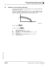
Page 23: ...according to IEC 60034 1 2017 Table 12 by which the thermal motor torque has to be reduced depending on the installation altitude H H 0 0 2 0 4 0 6 0 8 1 0 1 2 0 1000 m 2000 m 3000 m 4000 m 5000 m fAH...

Page 24: ...ll the drive units in the mounting position M3 after consultation with SEW EURODRIVE SEW EURODRIVE delivers drive units ordered for universal operation in mounting po sitions M1 M2 M4 M5 M6 with an en...

Page 25: ...ate it as follows For designs with the breather valve screwed in Check whether the breather valve is activated If not you have to re move the transport fixture of the breather valve before you start u...

Page 26: ...with an included pressure compensation fitting option PE you must in stall the fitting depending on the mounting position used The tightening torque is 4 0 Nm The following table shows the installati...

Page 27: ...stomer shaft design 4 5 1 Installation notes 1 Apply NOCO fluid and spread it thoroughly 21513616267 21513618699 2 Mount the shaft and secure it axially using a mounting device makes installation easi...

Page 28: ...ery 4 Retaining ring 2 Lock washer 6 Customer shaft 3 Washer 2B Installation with the SEW EURODRIVE assembly disassembly kit1 Customer shaft with contact shoulder 1 2 3 4 B 6 21513626507 1 Observe cha...

Page 29: ...4 5 C 21513628939 1 Observe chapter Technical data and dimension sheets Design notes for gear units with hollow shaft and key 1 Retaining screw 4 Retaining ring 2 Lock washer 5 Spacer tube 3 Washer 6...

Page 30: ...s The following description only applies when the drive is assembled using the SEW EURODRIVE assembly disassembly kit see previous description points 2B or 2C 1 Loosen the retaining screw 1 2 Remove p...

Page 31: ...rating Instructions MOVIGEAR classic 31 5 Screw the retaining screw 1 back in Now you can force the drive off the shaft by tightening the bolt 1 4 7 8 6 21513728267 1 Retaining screw 7 Fixed nut 4 Ret...

Page 32: ...ed gear unit with TorqLOC customer shaft without contact shoulder 1 Clean the customer shaft and the inside of the hollow shaft Ensure that all traces of grease or oil are removed 2 Install the stop r...

Page 33: ...ulder Operating Instructions MOVIGEAR classic 33 5 Push the gear unit onto the customer shaft 21528908171 6 Preassemble the torque arm on the plant structure holding fixture do not tighten the screws...

Page 34: ...he stop ring to the bushing Mark the position of the stop ring 21528915467 9 Remove the torque arm from the holding fixture plant structure 21528917899 10 Pull the gear unit off the customer shaft unt...

Page 35: ...he appropriate torque as specified in the table below 9007220783054347 Type Tightening torque Standard design Stainless steel MGFT 1 18 Nm 7 5 Nm 13 Push the bushing and the gear unit onto the custome...

Page 36: ...ened and slide the shrink disk onto the hollow shaft 9007220783624843 16 Slide the counter bushing onto the customer shaft and into the hollow shaft N O C O F L U I D 9007220783627275 17 Ensure the sh...

Page 37: ...ter rings of the shrink disk are parallel 9007220783634571 21 Tighten the locking screws by working round several times from one bolt to the next not in diametrically opposite sequence The exact value...

Page 38: ...unted gear unit with TorqLOC customer shaft without contact shoulder Operating Instructions MOVIGEAR classic 38 0 mm s 0 mm 0 mm 21528898443 23 Securely tighten the torque arm observe chapter Torque a...

Page 39: ...gear unit with TorqLOC customer shaft with contact shoulder Shaft mounted gear unit with TorqLOC customer shaft with contact shoulder 1 Clean the customer shaft and the inside of the hollow shaft Ensu...

Page 40: ...contact shoulder Operating Instructions MOVIGEAR classic 40 3 Slide the bushing onto the customer shaft 0 mm 21528993931 4 Apply NOCO fluid on the bushing and spread thoroughly N O C O FLU ID 2152899...

Page 41: ...ned and slide the shrink disk onto the hollow shaft 9007220783742219 7 Slide the counter bushing onto the customer shaft and into the hollow shaft N O C O F L U I D 9007220783744651 8 Ensure the shrin...

Page 42: ...of the shrink disk hand tight and ensure that the outer rings of the shrink disk are parallel 9007220783722763 12 Tighten the locking screws by working round several times from one bolt to the next n...

Page 43: ...t with contact shoulder Operating Instructions MOVIGEAR classic 43 14 The remaining gap between counter bushing and hollow shaft end must be 0 mm 0 mm s 0 mm 21528986635 15 Mount the torque arm and ti...

Page 44: ...cking screws one after the other by a quarter rotation each to avoid tilting the outer rings 21528210571 2 Unscrew the locking screws evenly one after the other Do not remove the locking screws comple...

Page 45: ...e reinstalled Clean and lubricate the shrink disk if it is dirty Lubricate the tapered surfaces with one of the following solid lubricants Lubricant Mo S2 Sold as Molykote 321 lube coat Spray Molykote...

Page 46: ...es Disconnect the drive unit from the power supply and safeguard it against uninten tional power up before you start working on it Equip the input and output elements with a touch guard 4 9 1 Installi...

Page 47: ...er In certain individual cases e g through shaft you cannot install the safety cover In these cases the safety cover is not necessary if the system or unit manufacturer provides corresponding componen...

Page 48: ...quality 8 8 to fasten torque arms INFORMATION The bolts required can be enclosed with delivery when required 4 10 1 MGF T1 torque arm Installation options The following figure shows the MGF T1 torque...

Page 49: ...hot surfaces Serious injuries Let the devices cool down before touching them 4 11 1 Blanking plugs Tighten the plastic blanking plugs included in the delivery by SEW EURODRIVE with 2 5 Nm Example The...

Page 50: ...pieces M16 1 5 5 to 9 mm 4 0 Nm 18204805 10 pieces M25 1 5 11 to 16 mm 7 0 Nm EMC cable glands stainless steel 18216366 10 pieces M16 1 5 5 to 9 mm 4 0 Nm 18216382 10 pieces M25 1 5 11 to 16 mm 7 0 N...

Page 51: ...nstructions MOVIGEAR classic 51 4 11 3 Cover Proceed as follows when installing the cover Insert the screws and tighten them in diametrically opposite sequence step by step with a tightening torque of...

Page 52: ...or DIN VDE 0100 540 Establish a connection over a wide surface area between the drive unit and the mounting rail To do so use a ground strap HF litz wire for example to connect the drive unit and the...

Page 53: ...M6 3884960907 Tightening torque on cable gland Tightening torque on M6 nut for stud bolt Part number M16 cable gland with M6 stud bolt 4 0 Nm 3 0 Nm 08189234 M25 cable gland with M6 stud bolt 7 0 Nm...

Page 54: ...with cage clamp terminals Terminals X2 for motor connection Observe the permitted cable cross sections for installation Terminals X2 for motor connection Connection cross sec tion mm2 0 5 mm2 6 0 mm2...

Page 55: ...the terminals only designs with cage clamp terminals Activating terminals X2 for motor connection Adhere to the following sequence when activating the terminals X2 for motor connec tion Terminals X2...

Page 56: ...out pushing the activation button Connect conductor after pressing the activation button 22904860811 1 2 22904932619 The following conductors can be installed directly without tool up to two cross sec...

Page 57: ...ies The permitted tightening torque for the screw is 2 0 2 4 Nm Observe the following notes regarding PE connection Prohibited assembly Recommendation Assembly with forked cable lug Permitted for all...

Page 58: ...E B and SEW EURODRIVE controller MOVI PLC with CCU Observe the installation notes in the documentation of the inverter controller that you use 2 2 2 2 2 2 2 X30 2 2 2 2 0 1 2 3 2 2 2 4 5 6 MOVITRAC LT...

Page 59: ...following figure shows a schematic installation topology with the MOVIDRIVE modular application inverter and MOVI C CONTROLLER from SEW EURODRIVE Observe the installation notes in the documentation o...

Page 60: ...ver is removed INFORMATION It is essential that you observe the wiring instructions in the documentation of the fre quency inverter that you use The following figure shows the terminal assignment of t...

Page 61: ...model for thermal protection provid ing your inverter supports such functions 5 6 1 PK PT1000 temperature sensor NOTICE Damage to the temperature sensor and the motor winding caused by excessive test...

Page 62: ...urve INFORMATION The temperature sensor is unipolar which means that interchanging the incoming cables does not change the measurement result The following figure shows a typical characteristic curve...

Page 63: ...e unit is undamaged and not blocked The measures stipulated in chapter Extended storage of motors are performed after extended storage periods All connections are installed correctly The direction of...

Page 64: ...Oil leaking from the gear unit cover Gear unit cover seal leak ing Consult SEW EURODRIVE Service Oil leaking from the con nection box Internal seal defective Consult SEW EURODRIVE Service Oil leaking...

Page 65: ...han 100 C Overload Measure power use larger drive unit or reduce load if necessary check travel profile Ambient temperature too high Observe permitted temper ature range Insufficient cooling Correct c...

Page 66: ...Extended storage 7 3 1 Drive NOTICE Volatilization of the VCI anti corrosion agent Possible damage to property Drive units must be kept tightly closed until they are started up INFORMATION For storag...

Page 67: ...tion Check corrosion protection Tropical Asia Africa Central and South America Aus tralia New Zealand ex cluding tem perate zones Packed in containers with desiccant and moisture indicator sealed in...

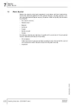
Page 68: ...al company If possible divide the product into the follow ing categories Iron steel or cast iron Stainless steel Magnets Aluminum Copper Electronic parts Plastics The following materials are hazardous...

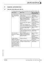
Page 69: ...t customer site In the event of a leakage at the output oil seal Change the oil seal Qualified personnel at customer site In the event of any other leakage Contact SEW EURODRIVE Service SEW EURODRIVE...

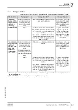
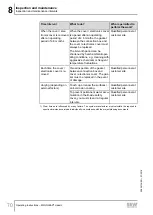
Page 70: ...ture fluctuations Qualified personnel at customer site Each time the cover electronics cover is re moved Visual inspection of the gasket between connection box and cover electronics cover The gas ket...

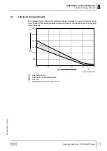
Page 71: ...he lubricant change intervals for normal ambient condi tions In case of severe aggressive ambient conditions the lubricant must be changed more frequently 5000 10000 15000 20000 25000 30000 h 120 C 11...

Page 72: ...utput shaft against rotation WARNING Risk of burns due to hot surfaces and hot gear unit oil Serious injuries Let the devices cool down before touching them Remove the screw plugs and the breather val...

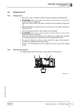
Page 73: ...figure below 4 Place an adequate container underneath the oil drain plug 2 5 WARNING Risk of burns due to hot gear oil Serious injuries Let the devices cool down before touching them Remove the lowes...

Page 74: ...ole 2 The oil viscosity and type synthetic that are to be used are determined by SEW EURODRIVE specifically for each order This information is noted in the order confirmation and on the drive unit s n...

Page 75: ...is a sufficient grease reservoir between the dust lip and sealing lip depending on the type of gear unit If you use double oil seals fill one third of the gap with grease Do not install the oil seal o...

Page 76: ...otor to break down For this reason you must clean the drives at regular intervals after one year at the latest to ensure a sufficiently large area for heat dissipation Insufficient heat dissipation ca...

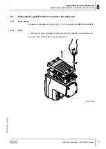
Page 77: ...8 9 Replacing the gasket between connection box and cover 8 9 1 Spare part kit The gasket is available as a spare part 1 10 or 50 pieces from SEW EURODRIVE 8 9 2 Steps 1 Observe the notes in chapter P...

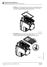
Page 78: ...to prop erty Make sure not to damage the sealing surfaces when removing the gasket Remove the old gasket completely from the connection box 21514108299 4 CAUTION Risk of injury due to sharp edges Cut...

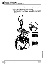
Page 79: ...ing the gasket between connection box and cover Operating Instructions MOVIGEAR classic 79 5 Place the new gasket on the connection box and fix it in position with the retaining nubs 1 1 22361594123 1...

Page 80: ...on and startup of the drive unit using the applicable operating instructions 7 Place the cover on the connection box again and fasten it Proceed as follows when installing the cover Insert the screws...

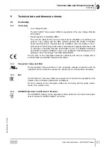
Page 81: ...n about EMC compliant installation refer to the publication Electromagnetic Com patibility in Drive Technology from SEW EURODRIVE The CE mark on the nameplate represents conformity with the Low Voltag...

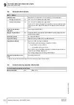
Page 82: ...65 in accordance to EN 60529 housing closed and all cable entries sealed Operating mode S1 DB EN 60034 1 Type of cooling Natural cooling to DIN 41751 and EN 61800 5 1 Installation altitude h Up to h 1...

Page 83: ...is re scaled towards the origin minimized The thermal operating point based on rms torque and thermally effective speed of the application must be below the re scaled characteristic curve M 0 T U n N...

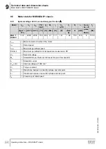
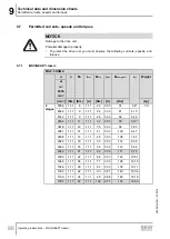
Page 84: ...V Nm A mH Hz MGF 1 DSM C 1 38 2000 2000 150 400 2 1 1 11 141 1 89 15 5 31 8 8 133 3 Jmot Mass moment of inertia of the motor nN Rated speed nmax Maximum permitted speed PK limit Maximum permitted mot...

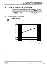
Page 85: ...or temperature Type PK PT1000 Total resistance at 20 25 C 1050 R 1150 Test current 3 mA 9 6 1 Typical characteristic curve of PK PT1000 INFORMATION The temperature sensor is unipolar which means that...

Page 86: ...A Nm A Nm kg 2 stages 555 6 1 11 8 1 11 23 3 33 74 3 6 7 0 484 3 1 11 9 1 11 26 3 33 81 4 13 451 2 1 11 9 1 11 28 3 33 82 4 43 390 2 1 11 11 1 11 32 3 33 90 5 13 361 8 1 11 12 1 11 35 3 33 94 5 53 309...

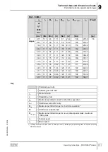
Page 87: ...190 41 85 45 6 1 11 76 0 92 114 1 37 171 43 86 44 5 1 11 88 1 04 128 1 51 192 44 92 41 7 1 11 80 0 88 120 1 32 180 48 01 38 5 1 11 94 0 96 128 1 30 192 51 94 35 7 1 11 97 0 92 128 1 21 192 56 01 Key...

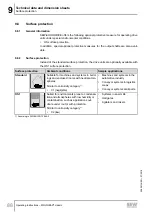
Page 88: ...ionally available with the OS1 surface protection Surface protection Ambient conditions Sample applications Standard Suitable for machines and systems in build ings and enclosed rooms with neutral atm...

Page 89: ...less steel standard when using the design for use in wet areas Surface protection with high quality material Particularly demanding applications in terms of surface protection 9 8 4 NOCO fluid As stan...

Page 90: ...1 5 6 8 Nm 18247350 EMC cable gland brass nickel plated 10 pieces M16 1 5 4 Nm 5 to 9 mm 18204783 10 pieces M25 1 5 7 Nm 11 to 16 mm 18204805 EMC cable gland made of stainless steel 10 pieces M16 1 5...

Page 91: ...are possible for MOVIGEAR classic MGF 1 DSM C drive units Specified mounting position M1 or M2 or M3 or M4 or M5 or M6 Universal operation in mounting positions M1 M2 M4 M5 M6 Mounting positions M1 to...

Page 92: ...on sheets Mounting positions Operating Instructions MOVIGEAR classic 92 9 10 2 Mounting position sheet 9007203827249931 Mounting position M3 only possible after consultation with SEW EURODRIVE Breathe...

Page 93: ...1 DSM C 2 stages Gear ratio i Fill quantities in liters for mounting positions M1 M2 M3 M4 M5 M6 Gear ratio i Fill quantities in liters for mounting positions M1 M2 M3 M4 M5 M6 56 01 0 36 l 19 90 0 4...

Page 94: ...r use the lubricants at temperat ures outside the recommended temperature range SEW EURODRIVE does not assume liability The lubricant recommendation in the lubricant table in no way represents a guar...

Page 95: ...e preselection of a suitable lubricant The exact upper and lower temperature limits for project planning are specified in the table with the respective trade name 15 40 25 30 ISO SAE NLGI CLP HC NSF H...

Page 96: ...y not be undershot in operation 2 Trade name 3 Factory filling for these countries BR Brazil CN China DE Germany FR France US United States 4 Manufacturer 5 Highest oil sump temperature in C1 6 Approv...

Page 97: ...mpatibility Approved application temperature range of the oil seals Oil seal Material class Permitted Oil sump temperature FKM 25 C to 115 C FKM PSS 25 C to 115 C Limitations of use of oil seals with...

Page 98: ...plains what they mean Abbreviation icon Meaning Synthetic lubricant marked gray CLP HC Synthetic hydrocarbons polyalphaolefin PAO Lubricant for the food processing industry NSF H1 compliant 4 Observe...

Page 99: ...bricant compatibil ity with oil seals VG 220 0 100 50 60 25 50 30 4 50 ISO SAE NLGI CLP HC PSS VG 150 C Mobil T O T A L Sh ll e FUCHS LUBRICATION remer egui Mobil SHC 630 Mobil SHC 629 25 110 30 100 M...

Page 100: ...by the customer however L12 must be DK 9 12 1 Installation SEW EURODRIVE recommends 2 variants for installing the hollow shaft and key on the input shaft of the driven machine customer shaft 1 Use th...

Page 101: ...25 8 8 20 1 Up to a distance of at least 1 5 DK the diameter of the customer shaft must be DKh6 and with the other length DKg6 2 Position of retaining ring INSIDE The installation length of the custom...

Page 102: ...nstallation without contact shoulder 5 Retaining screw for assembly 2 Forcing washer for disassembly 7 Fixed nut for disassembly 8 The short retaining screw delivered as standard is not required Custo...

Page 103: ...MS given in the fol lowing table Gear unit type DH7 DK 1 L12 Key L8 C7 L15 As sembly disas sembly kit Supplied re taining screw MS Width Type mm mm mm mm mm mm mm Part num ber ISO 4017 Nm MGFA 1 20 20...

Page 104: ...holes according to DIN 332 shape DR 7 to 10 mm M3 10 to 13 mm M4 13 to 16 mm M5 16 to 21 mm M6 21 to 24 mm M8 24 to 30 mm M10 30 to 38 mm M12 38 to 50 mm M16 Keys according to DIN 6885 domed type Hol...

Page 105: ...9 Technical data and dimension sheets Dimension drawings Operating Instructions MOVIGEAR classic 105 9 13 2 MGF 1 DSM C 25805134 EN 07 2018...

Page 106: ...9 Technical data and dimension sheets Dimension drawings Operating Instructions MOVIGEAR classic 106 25805134 EN 07 2018...

Page 107: ...mension drawings Operating Instructions MOVIGEAR classic 107 9 13 3 Shaft types MGFAS C mm D H7 D7 L4 L8 L9 O8 T U ISO 4017 MGFAS1 C 20 35 17 5 73 6 10 106 22 8 6 M6 16 8 8 MGFAS1 C 25 35 17 5 73 8 17...

Page 108: ...9 Technical data and dimension sheets Dimension drawings Operating Instructions MOVIGEAR classic 108 MGFTS C mm D4 h11 D 0 1 M4 O8 5 LK 5 DIN 509 MGFTS1 C 20 20 1 28 157 151 F1 0 2 25805134 EN 07 2018...

Page 109: ...esh Tel 88 01729 097309 salesdhaka seweurodrivebangladesh com Belarus Sales Minsk Foreign unitary production enterprise SEW EURODRIVE RybalkoStr 26 220033 Minsk Tel 375 17 298 47 56 298 47 58 Fax 375...

Page 110: ...22612 Fax 86 22 25323273 http www sew eurodrive cn info sew eurodrive cn Assembly Sales Service Suzhou SEW EURODRIVE Suzhou Co Ltd 333 Suhong Middle Road Suzhou Industrial Park Jiangsu Province 215021...

Page 111: ...85 http www copam egypt com copam copam egypt com Estonia Sales Tallin ALAS KUUL AS Reti tee 4 75301 Peetri k la Rae vald Harjumaa Tel 372 6593230 Fax 372 6593231 http www alas kuul ee veiko soots ala...

Page 112: ...Ernst Blickle Stra e 1 76676 Graben Neudorf Tel 49 7251 75 1710 Fax 49 7251 75 1711 scc mechanik sew eurodrive de Electronics SEW EURODRIVE GmbH Co KG Ernst Blickle Stra e 42 76646 Bruchsal Tel 49 72...

Page 113: ...EURODRIVE India Private Limited Plot No 4 GIDC POR Ramangamdi Vadodara 391 243 Gujarat Tel 91 265 3045200 Fax 91 265 3045300 http www seweurodriveindia com salesvadodara seweurodriveindia com Assembl...

Page 114: ...ry Coast Rue des P cheurs Zone 3 26 BP 916 Abidjan 26 Tel 225 21 21 81 05 Fax 225 21 25 30 47 info sew eurodrive ci http www sew eurodrive ci Japan Assembly Sales Service Iwata SEW EURODRIVE JAPAN CO...

Page 115: ...rial Qu retaro C P 76220 Quer taro M xico Tel 52 442 1030 300 Fax 52 442 1030 301 http www sew eurodrive com mx scmexico seweurodrive com mx Sales Service Puebla SEW EURODRIVE MEXICO S A de C V Calzad...

Page 116: ...al Fernando de la Mora Barrio Bernardino Tel 595 991 519695 Fax 595 21 3285539 sewpy sew eurodrive com py Peru Assembly Sales Service Lima SEW EURODRIVE DEL PERU S A C Los Calderos 120 124 Urbanizacio...

Page 117: ...rvice Celje Pakman Pogonska Tehnika d o o UI XIV divizije 14 3000 Celje Tel 386 3 490 83 20 Fax 386 3 490 83 21 pakman siol net South Africa Assembly Sales Service Johannesburg SEW EURODRIVE PROPRIETA...

Page 118: ...w ch info imhof sew ch Taiwan Sales Taipei Ting Shou Trading Co Ltd 6F 3 No 267 Sec 2 Tung Huw S Road Taipei Tel 886 2 27383535 Fax 886 2 27368268 Telex 27 245 sewtwn ms63 hinet net http www tingshou...

Page 119: ...Box 481 Bridgeport New Jersey 08014 Tel 1 856 467 2277 Fax 1 856 845 3179 csbridgeport seweurodrive com Midwest Region SEW EURODRIVE INC 2001 West Main Street Troy Ohio 45373 Tel 1 937 335 0036 Fax 1...

Page 120: ...cs Malfunctions of the mechanical drive 64 Dimension drawings 104 MGF 1 DSM C 105 Notes 104 E EAC 81 Electrical connection 11 Embedded safety notes 6 EMC cable glands Overview 90 Equipotential bonding...

Page 121: ...tomer shaft with contact shoulder 39 Shaft mounted gear unit with TorqLOC cus tomer shaft without contact shoulder 32 Torque arm 48 Mounting positions 91 N Nameplate Drive unit 18 Nameplate position...

Page 122: ...tartup 63 Safety notes 12 Startup notes 63 Storage conditions 67 Surface protection 88 T Target group 8 Technical data 81 Current carrying capacity of terminals plug con nectors 82 Design notes 100 Di...

Page 123: ......
Page 124: ...SEW EURODRIVE Driving the world SEW EURODRIVE GmbH Co KG Ernst Blickle Str 42 76646 BRUCHSAL GERMANY Tel 49 7251 75 0 Fax 49 7251 75 1970 sew sew eurodrive com www sew eurodrive com...

Reviews: