30
Compact Operating Instructions – MOVIMOT® MM..D with DRS/DRE/DRP AC Motor
6
Description of the DIP switches S1
"Easy" Startup
6.3
Description of the DIP switches S1
6.3.1
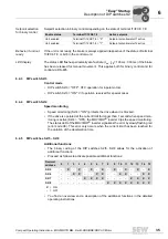
DIP switches S1/1 – S1/4
Selecting the RS-485 address of the MOVIMOT
®
drive via binary coding
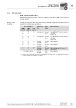
Set the following addresses depending on how the MOVIMOT
®
inverter is controlled:
6.3.2
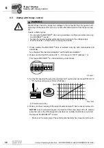
DIP switch S1/5
Motor protection switched on / off
When MOVIMOT
®
is installed close to the motor, the motor protection function must be
deactivated.
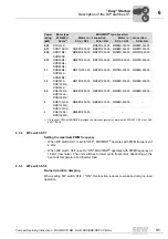
To ensure that the motor is protected all the same, a TH (bimetallic thermostat) must be
installed. The TH opens the sensor circuit when the nominal response temperature is
reached (see field distributor manual).
6.3.3
DIP switch S1/6
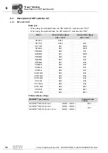
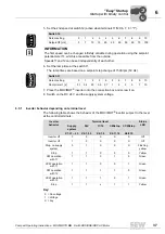
Lower motor power rating
• When activated, DIP switch S1/6 can be used to assign the MOVIMOT
®
inverter to
a motor with a lower power rating. The nominal unit power is not affected.
• When using a motor with a lower power rating, the MOVIMOT
®
inverter is one power
level above the motor. This is why you can increase the overload capacity of the
drive. A higher current can be provided briefly, leading to higher torque ratings.
• The aim of this switch S1/6 is to achieve short-term utilization of the motor's peak
torque. The unit's current limit remains the same regardless of the switch setting. The
motor protection function is adjusted depending on the switch setting.
• Stall protection for the motor is not possible in this operating mode (S1/6 = "ON").
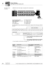
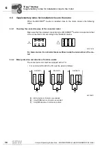
Decimal
address
0
1
2
3
4
5
6
7
8
9
10
11
12 13 14 15
S1/1
–
X
–
X
–
X
–
X
–
X
–
X
–
X
–
X
S1/2
–
–
X
X
–
–
X
X
–
–
X
X
–
–
X
X
S1/3
–
–
–
–
X
X
X
X
–
–
–
–
X
X
X
X
S1/4
–
–
–
–
–
–
–
–
X
X
X
X
X
X
X
X
X
= ON
– = OFF
Control
RS-485 address
Binary control
0
Via keypad (MLG..A, MBG..A)
1
Via fieldbus interface (MF..)
1
Via MOVIFIT
®
MC (MTM..)
1
Via intelligent fieldbus interface (MQ..)
1 – 15
Via RS-485 master
1 – 15
Via MWF11A setpoint converter
1 – 15
0
0
I


