Compact Operating Instructions – MOVIMOT® MM..D with DRS/DRE/DRP AC Motor
37
6
Startup with binary control
"Easy" Startup
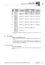
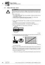
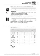
5. Set the 2nd speed at switch f2 (active when terminals f1/f2 X6, 7, 8 = "1").
6. Set the ramp time at the switch t1.
The ramp times are based on a setpoint step change of 1500 rpm (50 Hz).
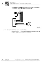
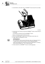
7. Place the MOVIMOT
®
inverter onto the connection box and screw it on.
8. Switch on the DC 24 V and the supply system voltage.
6.5.1
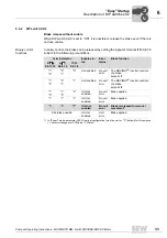
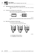
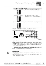
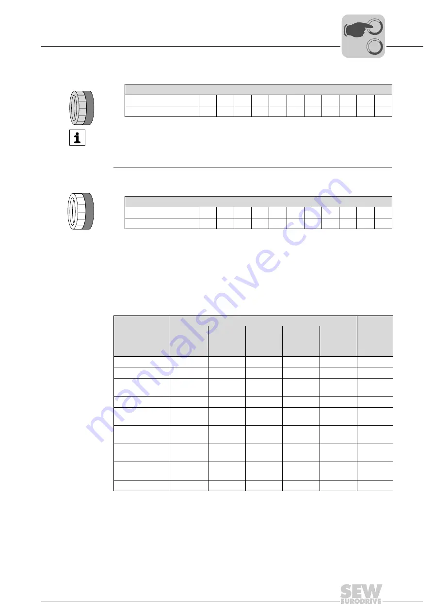
Inverter behavior depending on terminal level
The following table shows the behavior of the MOVIMOT
®
inverter subject to the level
at the control terminals:
Key:
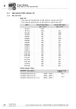
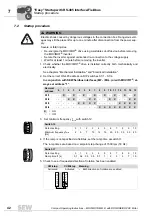
Switch f2
Detent setting
0
1
2
3
4
5
6
7
8
9
10
Setpoint f2 [Hz]
5
7
10
15
20
25
35
50
60
70
100
3
4
5
6
7
8
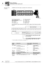
INFORMATION
The first speed can be changed infinitely variable during operation using the setpoint
potentiometer f1, which is accessible from the outside.
Speeds f1 and f2 can be set independently of each other.
Switch t1
Detent setting
0
1
2
3
4
5
6
7
8
9
10
Ramp time t1 [s]
0,1
0,2
0,3
0,5
0,7
1
2
3
5
7
10
3
4
5
6
7
8
Inverter
behavior
Terminal level
Status
LED
Supply
system
24V
f1/f2
CW/stop
CCW/stop
X1:L1 – L3
X6:1,2,3
X6:7,8
X6:11,12
X6:9,10
Inverter off
0
0
X
X
X
Off
Inverter off
1
0
X
X
X
Off
Stop, no supply
system
0
1
X
X
X
Flashing
yellow
Stop
1
1
X
0
0
Yellow
CW operation
with f1
1
1
0
1
0
Green
CCW operation
with f1
1
1
0
0
1
Green
CW operation
with f2
1
1
1
1
0
Green
CCW operation
with f2
1
1
1
0
1
Green
Stop
1
1
x
1
1
Yellow
0 = No voltage
1 = Voltage
X = Any
0
0
I


