38
Compact Operating Instructions – MOVIMOT® MM..D with DRS/DRE/DRP AC Motor
6
Supplementary notes for installation close to the motor
"Easy" Startup
6.6
Supplementary notes for installation close to the motor
When the MOVIMOT
®
inverter is installed close to the motor, observe the following
notes:
6.6.1
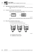
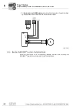
Checking the connection type of the connected motor
Make sure that the selected connection type of MOVIMOT
®
inverter corresponds to that
of the connected motor according to the illustration below.
For brake motors: Do not install brake rectifiers inside the terminal box of the mo-
tor!
6.6.2
Motor protection and direction of rotation enable
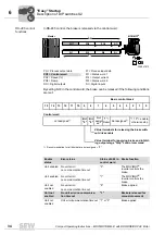
The connected motor must be equipped with a TH.
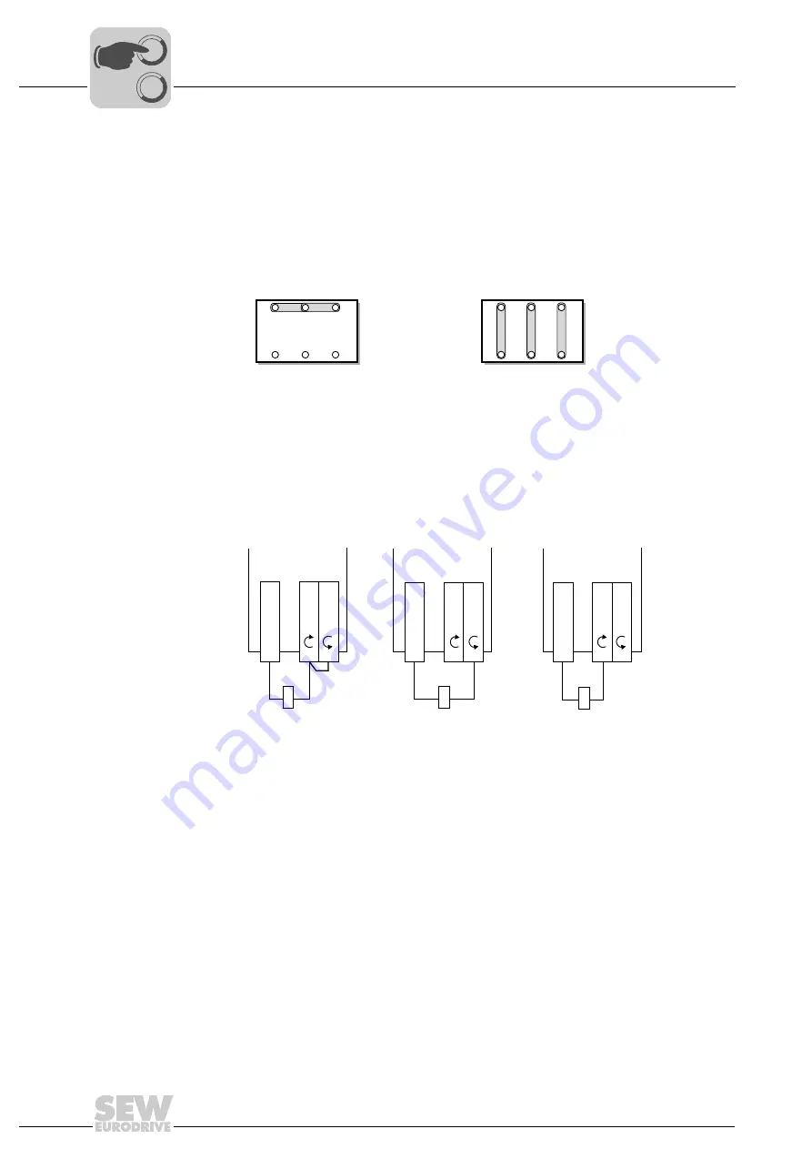
• For control via RS-485, the TH must be wired as follows:
337879179
U1
V1
W1
W2 U2 V2
U1
V1
W1
W2 U2 V2
483308811
[A] Both directions of rotation are enabled
[B] Only
CCW
direction of rotation is enabled
[C] Only
CW
direction of rotation is enabled
TH
TH
TH
MOVIMOT
®
MOVIMOT
®
MOVIMOT
®
A
B
C
24V X6: 1,2,3
R
X6: 11,12
L
X6: 9,10
24V X6: 1,2,3
R
X6: 11,12
L
X6: 9,10
24V X6: 1,2,3
R
X6: 11,12
L
X6: 9,10
0
0
I


