42
Compact Operating Instructions – MOVIMOT® MM..D with DRS/DRE/DRP AC Motor
7
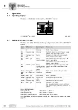
Startup procedure
"Easy" Startup with RS-485 Interface/Fieldbus
7.2
Startup procedure
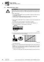
1. Check whether the MOVIMOT
®
drive is installed correctly both mechanically and
electrically.
See chapters "Mechanical Installation" and "Electrical Installation".
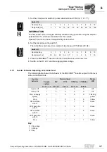
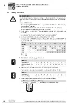
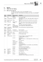
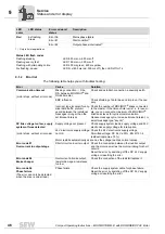
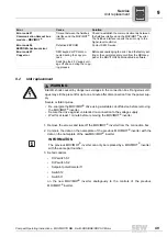
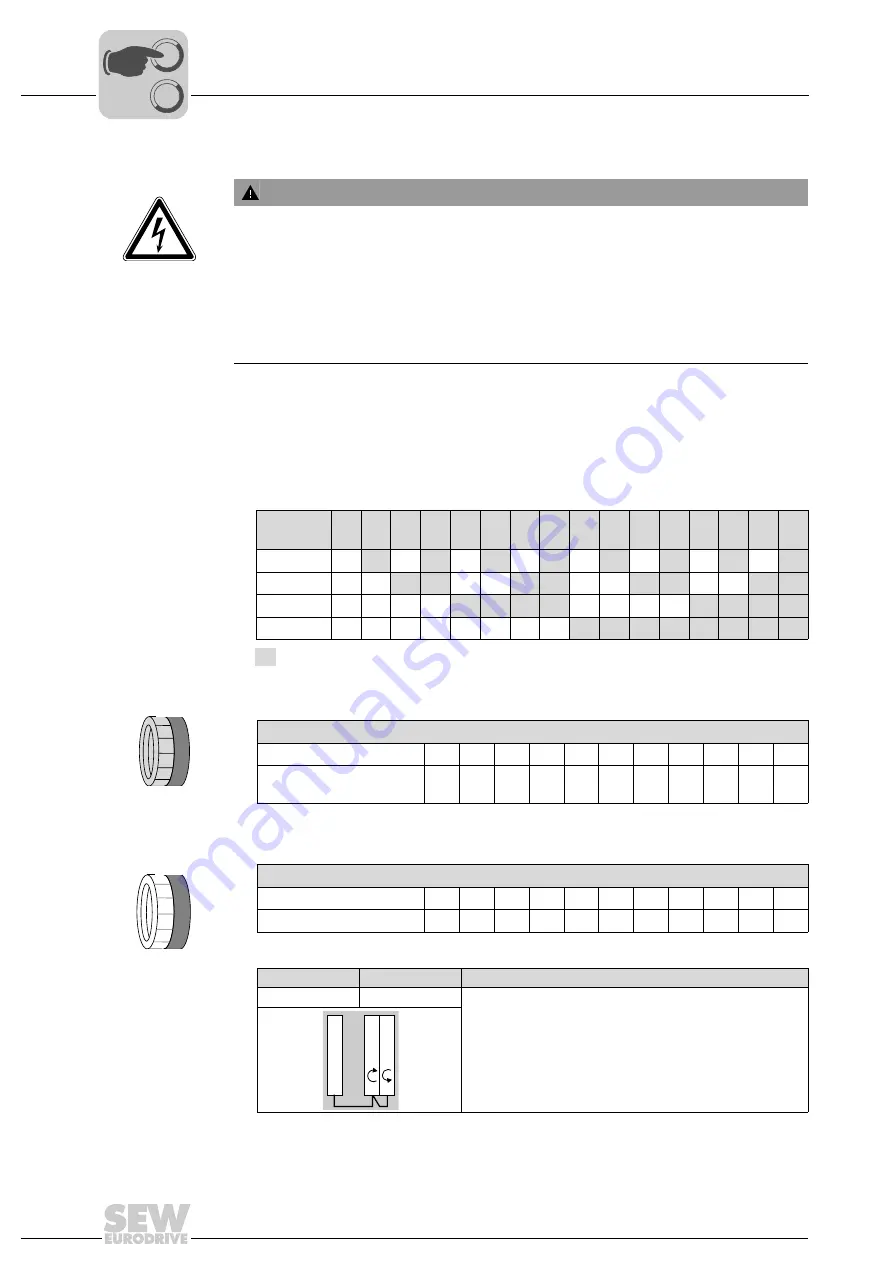
2. Set the correct RS-485 address on DIP switches S1/1 – S1/4.
In conjunction with SEW fieldbus interfaces (MF.. / MQ..) or with MOVIFIT
®
, al-
ways set address "1".
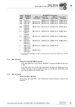
3. Set minimum frequency f
min
with switch f2.
4. If the ramp is not specified via fieldbus, set the ramp time at switch t1.
The ramp times are based on a setpoint step change of 1500 rpm (50 Hz).
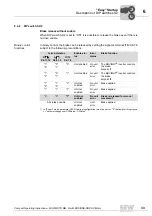
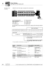
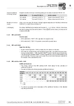
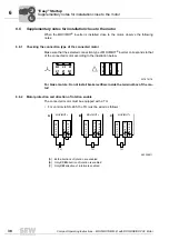
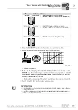
5. Check to see if requested direction of rotation has been enabled.
WARNING
Electric shock caused by dangerous voltages in the connection box. Dangerous volt-
ages may still be present for up to one minute after disconnection from the power sup-
ply.
Severe or fatal injuries.
• De-energize the MOVIMOT
®
drive using a suitable cut-off device before removing
the MOVIMOT
®
inverter.
• Secure the inverter against unintended re-connection to the voltage supply.
• Wait for at least 1 minute before removing the inverter.
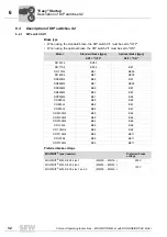
Decimal
address
0
1
2
3
4
5
6
7
8
9
10
11
12 13 14 15
S1/1
–
X
–
X
–
X
–
X
–
X
–
X
–
X
–
X
S1/2
–
–
X
X
–
–
X
X
–
–
X
X
–
–
X
X
S1/3
–
–
–
–
X
X
X
X
–
–
–
–
X
X
X
X
S1/4
–
–
–
–
–
–
–
–
X
X
X
X
X
X
X
X
X
= ON
–
= OFF
Switch f2
Detent setting
0
1
2
3
4
5
6
7
8
9
10
Minimum frequency f
min
[Hz]
2
5
7
10
12
15
20
25
30
35
40
Switch t1
Detent setting
0
1
2
3
4
5
6
7
8
9
10
Ramp time t1 [s]
0,1
0,2
0,3
0,5
0,7
1
2
3
5
7
10
CW/stop
CCW/stop
Meaning
Activated
Activated
•
Both directions of rotation are enabled
3
4
5
6
7
8
3
4
5
6
7
8
R
X6: 11,12
L
X6: 9,10
24V X6: 1,2,3
0
0
I


