22
Manual – MOVIPRO® SDC with DeviceNet Interface
4
Status and error messages
Installation Notes
4.4.2
Inverter status
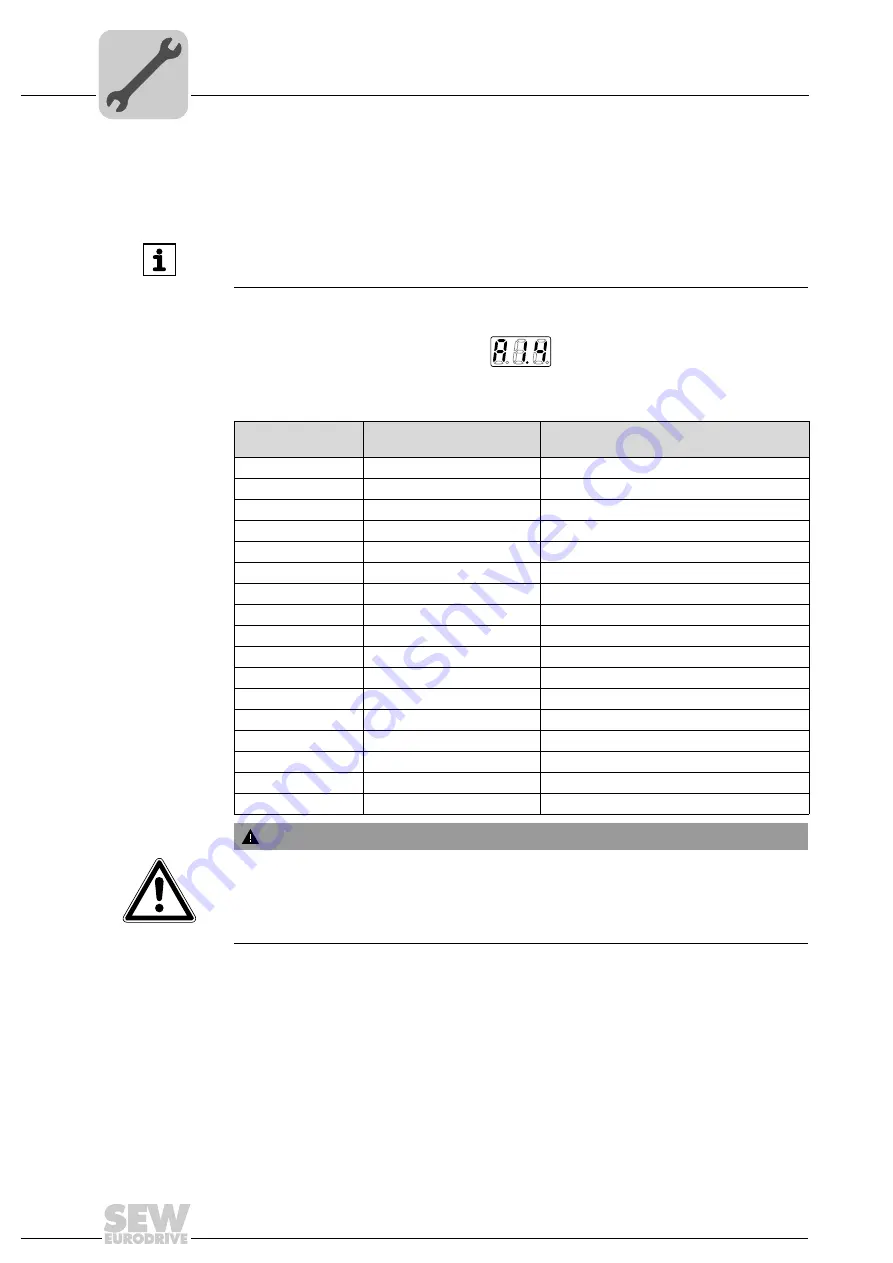
The inverter status is indicated by displaying the address/number of the axis and the cor-
responding status code in the form of A1.y.
The following figure shows the display for the "Enable" status of axis 1:
The following table shows the various status codes:
INFORMATION
The unit status display takes priority over the inverter status display. If the mainte-
nance switch is switched off of a fieldbus error occurs, no inverter status is displayed.
1820269707
7-segment display
Unit status
(high byte in status word 1)
Meaning
0
0
dec
DC 24 V operation (inverter not ready)
1
1
dec
Controller inhibit active
2
2
dec
No enable
3
3
dec
Standstill current
4
4
dec
Enable
5
5
dec
n-control (speed control)
6
6
dec
M-control (torque control)
7
7
dec
Hold control
8
8
dec
Factory setting
9
9
dec
Limit switch contacted
A
10
dec
Technology option
c
12
dec
IPOS
plus®
reference travel
d
13
dec
Flying start
E
14
dec
Calibrate encoder
F
Error code (page 133)
Error indicator (flashing)
U
17
dec
"Safe Stop" active
• (blinking dot)
–
Application module running
WARNING
Incorrect interpretation of display
U = "Safe stop" active
.
Severe or fatal injuries.
The display
U = "Safe stop" active
is not safety-related and must not be used as a
safety function.


