background image

Manual – MOVIPRO® SDC with DeviceNet Interface 

75

10

Startup assistant

Parameterization of MOVIPRO

®

10

Parameterization of MOVIPRO

®

10.1 Startup assistant

10.1.1 Encoder startup

1. Start MOVITOOLS

®

MotionStudio and create a new project. For more information,

refer to chapter "Operation of MOVITOOLS

®

 MotionStudio" (page 64).

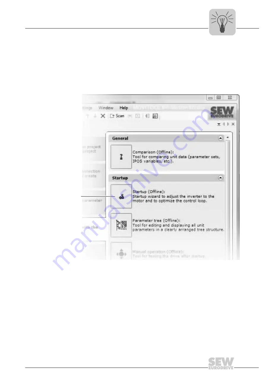
2. Click on the [Startup] button [1] to call the startup wizard. 

2097970443

[1] [Startup] button

[1]

Summary of Contents for MOVIPRO SDC

Page 1: ...Drive Technology Drive Automation System Integration Services Manual MOVIPRO SDC With DeviceNet Interface Edition 03 2010 16779215 EN ...

Page 2: ...SEW EURODRIVE Driving the world ...

Page 3: ...ielding and routing the bus cables 18 4 3 Setting the station address DeviceNet 19 4 4 Status and error messages 21 5 Configuration and Startup on the DeviceNet Fieldbus 25 5 1 Validity of the EDS files for MOVIPRO 25 5 2 Configuring the PLC and master DeviceNet scanner 26 5 3 Configuration examples in RSLogix 5000 29 6 DeviceNet Operating Characteristics 37 6 1 Process data exchange 37 6 2 Common...

Page 4: ...mmunication via Ethernet 68 9 5 Executing functions with the units 72 10 Parameterization of MOVIPRO 75 10 1 Startup assistant 75 10 2 Storing unit data 83 10 3 Overview of parameters 85 10 4 Explanation of the parameters 90 11 Service 130 11 1 Unit replacement 130 11 2 Service unit 132 11 3 MOVIPRO SDC error list 133 12 Additional Documentation 143 13 Address List 144 Index 145 ...

Page 5: ...ion safety notes Section safety notes do not apply to a specific action but to several actions pertaining to one subject The used symbols indicate either a general or a specific hazard This is the formal structure of a section safety note 1 2 3 Structure of the embedded safety notes Embedded safety notes are directly integrated in the instructions just before the descrip tion of the dangerous acti...

Page 6: ...s manual In such cases any liability for defects is excluded 1 5 Copyright notice 2009 SEW EURODRIVE All rights reserved Copyright law prohibits the unauthorized duplication modification distribution and use of this document in whole or in part 1 6 Other applicable documentation This manual does not replace the detailed operating instructions Only electrical special ists are allowed to install and...

Page 7: ...SDC Functional Safety Use only those components in safety applications that were explicitly designed and de livered for this purpose by SEW EURODRIVE 1 9 Hoist applications Hoist applications can only be implemented with MOVIPRO SDC under the follow ing conditions A hoist startup must be performed MOVIPRO is not designed for use as a safety device in hoist applications Use monitoring systems or me...

Page 8: ...ses this information to create the control program and loads it into the inverter MOVIPRO SDC then takes over the entire motion control Thus the application module takes load off the higher level controller Benefits The application modules offer the following benefits A wide range of functions A user friendly GUI Only the parameters necessary for the application must be entered Guided parameter se...

Page 9: ...odules are available for MOVIPRO SDC Bus positioning Extended positioning via bus Modulo positioning Table positioning Sensor based positioning via bus Automotive AMA0801 Bus positioning The Bus positioning application module has the following functions Variable and unlimited number of target positions Freely adjustable travel speed for positioning Maximum travel distance 32700 mm 1984436491 ...

Page 10: ...itioning application module has the following functions Variable number of target positions The travel speed for positioning and the acceleration and deceleration ramps are specified variably by the PLC Maximum travel distance 262100 mm Operation is possible with 4 instead of 6 process data words The variable specification of the ramp type is not used in this case 1984444811 ...

Page 11: ...selected when 4 process data words are used for control The acceleration or deceleration ramps can be specified using process data word 5 or 6 for control via 6 process data words For a non positive connection with slip between the motor shaft and application the distance measurement can be taken via an external incremental or absolute encoder The encoder must be mounted to the application without...

Page 12: ...MOVITOOLS MotionStudio Sensor based positioning The Sensor based positioning application module has the following functions Variable and unlimited number of target positions Freely adjustable travel speed changes can be made during travel for linear positioning ramps Maximum travel distance 32700 m 1984845707 ...

Page 13: ...n module makes it possible to implement lifting devices conveyor systems and machinery with drives that have to move at a synchronous angle to one another occasionally or permanently The Automotive AMA0801 application module has a selectable process data interface Setpoints specification is either variable or binary The program is used to control individual drives In synchronous operation mode the...

Page 14: ...the engineering PC and the MOVIPRO unit have the same IP address page 68 The engineering PC and the MOVIPRO unit have identical subnet masks The MOVIPRO can be addressed via the engineering PC using the ping command The following illustration gives an overview of the MOVIPRO startup procedure and lists other applicable documentation 1 Motor startup Refer to the operating instructions of the motor ...

Page 15: ...to configure the MOVIPRO 1 Start MOVITOOLS MotionStudio 2 Create a new project 3 Set the communication properties to Ethernet 4 Perform a unit scan 5 Mark the MOVIPRO unit 6 Right click on it and select Startup Startup from the context menu 7 Perform a motor startup page 78 8 Load the respective application module into MOVIPRO if necessary 9 Check whether the process data exchange between the cont...

Page 16: ...on on the assembly and the installation of MOVIPRO refer to the MOVIPRO SDC operating instructions For a simple application this section contains information on how to install the DeviceNet Function DeviceNet input Connection type M12 5 pole male A coded Wiring diagram 2264818187 Assignment No Name Function 1 Drain Shield equipotential bonding 2 V DC 24 V input 3 V Reference potential 4 CAN_H CAN ...

Page 17: ...le length depends on the baud rate setting Function DeviceNet output Connection type M12 5 pole female A coded Wiring diagram 2264816267 Assignment No Name Function 1 Drain Shield equipotential bonding 2 V DC 24 V output 3 V Reference potential 4 CAN_H CAN data line high 5 CAN_L CAN data line low 1 4 3 2 5 INFORMATION If the unit is the last station in the bus you must provide for a bus terminatio...

Page 18: ...etal housing or a metalized housing Connect the shielding in the connector over a wide surface area Apply the shielding of the bus cables on both ends Route signal and bus cables in separate cable ducts Do not route them parallel to power cables motor leads Use metallic grounded cable racks in industrial environments Route the signal cable and the corresponding equipotential bonding close to each ...

Page 19: ...es not interrupt the DeviceNet network Pro ceed as follows when removing the module 1 Loosen the knurled screws 2 Pull the DeviceNet module from the MOVIPRO unit to the front 3 Use DIP switches 1 to 6 to set the DeviceNet address The following example shows the settings of the DIP switches for DeviceNet address 17 INFORMATION Any changes to the station address during operation become effective aft...

Page 20: ...ine To prevent malfunctions in the bus system due to reflections etc the DeviceNet segment must be terminated using bus terminating resistors at the first and last physical stations 5 Once plugged in secure the DeviceNet module with both knurled screws 4 3 1 Setting the baud rate Use DIP switches 7 to 8 to set the baud rate DIP switch setting Significance DIP 1 ON 1 DIP 2 OFF 2 DIP 3 OFF 4 DIP 4 O...

Page 21: ... the highest priority is displayed 4 4 1 Unit status The following unit statuses are possible Display Description Maintenance switch is switched off Initialization Trying to establish a connection to all internal compo nents This can take several minutes after a unit replacement The connection has been established The statuses of the compo nents or the application are displayed after 3 s Flashing ...

Page 22: ...layed 1820269707 7 segment display Unit status high byte in status word 1 Meaning 0 0dec DC 24 V operation inverter not ready 1 1dec Controller inhibit active 2 2dec No enable 3 3dec Standstill current 4 4dec Enable 5 5dec n control speed control 6 6dec M control torque control 7 7dec Hold control 8 8dec Factory setting 9 9dec Limit switch contacted A 10dec Technology option c 12dec IPOSplus refer...

Page 23: ...atus Status Meaning Off Not switched on offline Unit is offline Unit is performing DUP MAC check Unit is switched off Flashing green Online and in operational mode The unit is online and no connection has been established DUP MAC check performed successfully A connection has not yet been established with a master Missing incorrect or incomplete configuration Lights up green Online operational mode...

Page 24: ... orange Data backup is created restored Lights up orange Boot process is active Flashing orange Firmware is being updated Flashing red No SD card plugged in File system of the SD card corrupt Boot process has failed Switch the unit off and back on again If the error occurs repeatedly contact the SEW Service staff LED status Status or cause of error Remedy Lights up green Gateway program is running...

Page 25: ...e to establish the DeviceNet net work with MOVIPRO Proceed as follows 1 Select the menu item Tools EDS Wizard in RSNetWorx 2 Select the EDS file and the ICON file The files will be installed For more details on how to install the EDS file refer to the Allen Bradley documentation for RSNetWorx 3 After installation the device is available in the device list under the entry Vendor SEW EURODRIVE GmbH ...

Page 26: ...t After adding the DeviceNet scanner to the I O configuration the DNT file containing the DeviceNet configuration is selected To view and edit the DeviceNet configuration RSNetWorx can be launched from this dialog In RSNetWorx for DeviceNet see following figure either perform an online scan or add the required devices to the graph by drag and drop The address given under the icon of the device mus...

Page 27: ...d Startup on the DeviceNet Fieldbus By reading the device properties in online mode the process data Pd configuration of MOVIPRO can be checked The Pd configuration parameter shows the number 1 64 of process data words PD that was set via RSNetWorx and defines the I O parameters for the DeviceNet scanner 2632314635 ...

Page 28: ...saved and downloaded the DeviceNet configuration to the scanner Depending on the DeviceNet configuration and the mapping rules in the scanner the data from and to DeviceNet units is packed into a DINT array that is transferred from the scanner to the local I O tags of the Logix processor In order not to have to search for the data from a certain device in this array manually the DeviceNet Tag Gene...

Page 29: ...guration as shown in chapter Configuring the PLC and master DeviceNet scanner page 26 3 Set the number of process data words of MOVIPRO to 8 4 You can now start integration into the RSLogix project Generate a controller tag with a user defined data type 1 to get a plain interface to the inverter s process data The description for the process input and output data of the controller tag can match th...

Page 30: ...tsRoutine In order to copy the data from the new data structure to MOVIPRO a CPS com mand is added into the MainRoutine that writes the data to the local I O These CPS commands are executed before the automatically generated by Devi ceNet Tag Generator DNet_Scanner_OutputsRoutine 6 Now the project is saved and uploaded to the PLC Set the PLC to RUN mode and set the Scanner CommandRegister Run to 1...

Page 31: ...us Now actual values can be read from MOVIPRO and setpoint values can be written 5 3 2 Access to parameters of MOVIPRO In order to get an easy to use read access to parameters of the MOVIPRO via explicit messages and the register object follow these steps 1 Create a user defined data structure SEW_Parameter_Channel 1968348683 2633115019 ...

Page 32: ...adParameterStart tag For message control select the ReadParameter tag 4 Click on in the MSG command to open the Message Configuration window Choose CIP Generic as the Message Type Fill the other fields in the following or der A Source Element ReadParameterRequest Index B SourceLength 12 C Destination ReadParameterResponse Index D Class 7hex E Instance 1 F Attribute 4hex G Service Code ehex The ser...

Page 33: ... After downloading the changes to the PLC the index of the parameter to be read can be entered at ReadParameterRequest Index Changing the ReadParameterStart control bit to 1 executes the read command once On response to the read request ReadParameterResponse Index should indicate the read index and ReadParameterResponse Data should contain the read data In this example the timeout delay of the MOV...

Page 34: ...parameter displays for example index subindex factor etc of the parameter Only a few changes are required for parameter write access Create the controller tags see following figure Create a rung to execute the WriteParameter command For the contact choose the WriteParameterStart tag For message control choose the WriteParameter tag Click on in the MSG command to open the Message Configuration wind...

Page 35: ...en into the pa rameter can be entered at WriteParameterRequest Index and WriteParameterRe quest Data Changing the WriteParameterStart control bit to 1 executes the write command once On response to the write request WriteParameterResponse Index should give the written index and WriteParameterResponse Data should contain the written data In this example the value C8hex 200 dec was written to the ti...

Page 36: ...o the SBus 1 of the PFH communication and control unit are accessed in the same way as the unit pa rameters of the PFH communication and control unit The only difference is that Read WriteParameterRequest SubChannel1 for example must be set to 3 and Read WriteParameterRequest SubAddress1 must be set to SBus address 20 In this example the value 150 rpm has been read from parameter P160 fixed setpoi...

Page 37: ... displayed in the device as timeout interval in index 8606 in the bus diagnostics in the parameter tree This timeout interval is retained in the device whenever the polled I O connection is dropped and the device switches to timeout status after the timeout interval has elapsed The timeout interval must not be altered using the PLC Editor or the IEC program be cause it can only be activated via th...

Page 38: ...t interval using the following formula tTimeout_Bit Strobe_IO 4 x tExpected_Packet_Rate_Bit Strobe_IO The expected packet rate is set using the connection object class 5 instance 3 attribute 9 The range of values runs from 0 ms to 65535 ms in 5 ms steps If the timeout time for the bit strobe I O messages has elapsed this connection type switches to timeout status Incoming bit strobe I O messages a...

Page 39: ...bject Attri bute Access Name Data type Default value hex Description 1 Get Vendor ID UINT 013B SEW EURODRIVE GmbH Co KG 2 Get Device Type UINT 0064 Manufacturer specific type 3 Get Product Code UINT 0011 Product no 17 MOVIPRO 4 Get Revision STRUCT of Revision of the identity object depends on firmware ver sion Major Revision USINT Minor Revision USINT 5 Get Status WORD See table Coding of attribut...

Page 40: ...110 At least one I O connection active Service code hex Name Instance 05 Reset X 0E Get_Attribute_Single X Attribute Access Name Data type Default value hex Description 1 Get Revision UINT 0002 Revision 2 Attribute Access Name Description 1 Get MAC ID According to DIP switch 0 63 2 Get Baud rate According to DIP switch 0 2 3 Get BOI 4 Get Set Bus off counter Error counter of the physical CAN inter...

Page 41: ...on object Instance Communication 1 Explicit message 2 Polled I O 3 Bit strobe I O Attribute Access Name 1 Get State 2 Get Instance type 3 Get Transport class trigger 4 Get Produce connection ID 5 Consume connection ID Get 6 Get Initial com characteristics 7 Get Produced connection size 8 Get Consumed connection size 9 Get Set Expected packet rate 12 Get Watchdog timeout action 13 Get Produced conn...

Page 42: ...t_Attribute_Single are used for ac cess The register object is specified so that INPUT objects can only be read whereas OUT PUT objects can be read and written This is why you may only access the parameter channel as follows Instance Type Resulting MOVILINK service with Get_Attribute_Single Set_Attribute_Single 1 INPUT READ parameter Invalid 2 OUTPUT READ WRITE parameter 3 OUTPUT READ WRITE VOLATI...

Page 43: ...UM READ MAXIMUM READ DEFAULT READ SCALING READ ATTRIBUTE WRITE WRITE VOLATILE Get_Attribute_Single Get_Attribute_Single Set_Attribute_Single Set_Attribute_Single Get_Attribute_Single Get_Attribute_Single Get_Attribute_Single Get_Attribute_Single Get_Attribute_Single Input Instance 1 Input Instance 4 Input Instance 5 Input Instance 6 Input Instance 7 Input Instance 8 Get_Attribute_Single Input Inst...

Page 44: ...RMATION Explanation of the attributes Attribute 1 indicates whether an error occurred during the previous access to the data field Attribute 2 indicates the direction of the instance Attribute 3 indicates the data length in bits Attribute 4 represents the parameter data When accessing attribute 4 the SEW parameter channel must be attached to the service telegram Name Data type Description Index UI...

Page 45: ...0 Supports parameter instances Bit 3 Parameters are stored in a non volatile manner 9 Get Configura tion Assem bly Interface UINT 0000 Configuration assembly is not sup ported Attribute Access Name Data type Default value hex Description 1 Set Get Parameter UINT 206C Parameter to be read or written See table Fieldbus parameters of MOVIPRO 2 Get Link Path Size USINT 00 Not used 3 Get Link Path Pack...

Page 46: ...table page 48 The table shows the proprietary error 10hex Illegal parameter index 6 3 2 Return codes of DeviceNet DeviceNet specific return codes are sent in the error message if the data format is not maintained during the transfer or if a service is performed which has not been imple mented The coding of these return codes is described in the DeviceNet specification see section General Error Cod...

Page 47: ...t is not possible to access the selected object for writing 0F Privilege violation Violation of access right 10 Device state conflict The current status of the device makes it impossible to perform the required service 11 Reply data too large The length of the transmitted data is longer than the size of the receive buffer 12 Reserved for DeviceNet 13 Not enough data The length of the transferred d...

Page 48: ...error 0x05 0x00 0xF1 Illegal Service 0x01 0xF2 No Response 0x02 0xF3 Different Address 0x03 0xF4 Different Type 0x04 0xF5 Different Index 0x05 0xF6 Different Service 0x06 0xF7 Different Channel 0x07 0xF8 Different Block 0x08 0xF9 No Scope Data 0x09 0xFA Illegal Length 0x0A 0xFB Illegal Address 0x0B 0xFC Illegal Pointer 0x0C 0xFD Not enough memory 0x0D 0xFE System Error 0x0E 0xD1 0xF0 Communication...

Page 49: ...in error class 0x08 Meaning 0x1F 0x00 No Error 0x10 Illegal Index 0x11 Not yet implemented 0x12 Read only 0x13 Parameter Blocking 0x14 Setup runs 0x15 Value too large 0x16 Value too small 0x17 Required Hardware does not exist 0x18 Internal Error 0x19 Access only via RS485 0x1A Access only via RS485 0x1B Parameter protected 0x1C Controller inhibit required 0x1D Value invalid 0x1E Setup started 0x1F...

Page 50: ...body Includes the class no instance no attribute no and the data Explicit message Parameter data message assists in addressing the DeviceNet objects Get_Attribute_Single Read service for a parameter Instance Instance of an object class Divides the object classes into additional sub groups MAC ID Media Access Control Identifier node address of the device M File Provides the data range between the P...

Page 51: ... possible to transmit data to the MOVIPRO across DeviceNet the following steps should help you to diagnose the error A Are the correct values for the process data words displayed in the parameter tree If yes continue with F B Is bit 0 in the DeviceNet control register of the PLC set to 1 to activate the exchange of process data C Are the process data words copied to the right offset in the Local I...

Page 52: ... platform MOVIPRO control word 4 DIO PO1 PO2 PO3 PO4 PO5 PO6 Master MOVIPRO Power section based on MOVIDRIVE platform MOVIPRO status word 12 DI PI1 PI2 PI3 PI4 PI5 PI6 Master 15 14 13 12 11 10 9 8 7 6 5 4 3 2 1 0 MOVIPRO 0 4 Reserved 0 5 Reset application 6 Reset system 7 Reserved 0 8 15 Reserved 0 Bit Meaning Explanation 0 4 Reserved 0 reserved 5 Reset application If there is an error in the PFH ...

Page 53: ... 9 8 7 6 5 4 3 2 1 0 MOVIPRO 0 Maintenance switch mains OFF 1 5 Reserved 0 6 MOVIPRO warning 7 MOVIPRO error 8 15 Unit status warning error num ber Bit 6 Bit 7 Assignment of bits 8 15 0 0 MOVIPRO unit status 1 0 MOVIPRO warning 0 1 MOVIPRO error Bit Diagnostic name via bus Function and coding 0 Maintenance switch mains OFF Maintenance switch mains OFF 1 Maintenance switch activated mains off 0 OK ...

Page 54: ...DO00 15 14 13 12 11 10 9 8 7 6 5 4 3 2 1 0 Master MOVIPRO 15 14 13 12 11 10 9 8 7 6 5 4 3 2 1 0 0 Binary input DI00 status of binary output DO00 1 Binary input DI01 status of binary output DO01 2 Binary input DI02 status of binary output DO02 3 Binary input DI03 status of binary output DO03 4 Binary input DI04 5 Binary input DI05 6 Binary input DI06 7 Binary input DI07 8 Binary input DI08 9 Binary...

Page 55: ...rm are assigned differently depending on the application module used The number of pro cess data words can vary between 1 6 depending on the application module 8 5 1 Speed controlled drive The process output input data words of a speed controlled drive no application module loaded are assigned as follows PO PO1 Control word 1 PO2 Setpoint speed PO3 Ramp PI PI1 Status word 1 PI2 Actual speed PI3 Ac...

Page 56: ...of rotation for motor potentiometer 9 10 Motor potentiometer accelera tion deceleration 11 12 Selection of the internal fixed setpoints n11 n13 and n21 n23 13 Changing the fixed setpoint 14 15 Reserved 0 Bit Meaning Explanation 0 Controller inhibit 0 Enable 1 Inhibit controller activate brake 1 Enable stop 0 Stop 1 Enable 2 Enable stop 0 Stop at the integrator or process ramp 1 Enable 3 Hold contr...

Page 57: ...on deceleration 10 9 0 0 No change 1 0 Down 0 1 Up 1 1 No change 11 12 Selection of the internal fixed set points n11 n13 and n21 n23 12 11 0 0 Speed setpoint via PO2 0 1 Internal setpoint n11 n21 1 0 Internal setpoint n12 n22 1 1 Internal setpoint n13 n23 13 Changing the fixed setpoint 0 Fixed setpoints of the active parameter set selectable via bit 11 12 1 Fixed setpoints of the other parameter ...

Page 58: ...e stop and emergency stop functions are not af fected by this process ramp When transmitting the process ramp via fieldbus system ramps t11 t12 t21 and t22 become ineffective Coding 1 digit 1 ms Range 100 ms 65 s Calculation 2 0 s 2000 ms 2000dec 07D0hex Status word 1 In addition to the most important status information in the basic status block status word 1 alternately contains information on th...

Page 59: ... rpm Active current By assigning a process input word ACTIVE CURRENT the power section provides the actual active current value in IN to the higher level automation system Coding 1 digit 0 1 IN 8 5 2 Bus positioning application module The process output and input data words of the Bus positioning application module are assigned as follows PO PO1 Control word 2 PO2 Setpoint speed PO3 Target positio...

Page 60: ... are assigned as follows PO PO1 Control word 2 PO2 Target pos high PO3 Target pos low PO4 Setpoint speed PO5 Acceleration ramp PO6 Deceleration ramp PI PI1 Status word PI2 Actual pos high PI3 Actual pos low PI4 Actual velocity PI5 Active current PI6 Unit utilization For further information refer to the following documentation Documentation Publication number MOVIDRIVE MDX61B Extended Bus Positioni...

Page 61: ...re assigned as follows PO PO1 Control word 2 PO2 Target pos high PO3 Target pos low PO4 Setpoint speed PO5 Acceleration ramp PO6 Deceleration ramp PI PI1 Status word PI2 Actual pos high PI3 Actual pos low PI4 Actual velocity PI5 Active current PI6 Unit utilization For further information refer to the following documentation Documentation Publication number MOVIDRIVE MDX60B 61B Modulo Positioning A...

Page 62: ...nsor based positioning via bus application module The process output and input data words of the Sensor based positioning application module are assigned as follows PO PO1 Control word 2 PO2 Setpoint speed PO3 Setpoint position PI PI1 Status word PI2 Actual velocity PI3 Actual position For further information refer to the following documentation Documentation Publication number MOVIDRIVE MDX61B Ta...

Page 63: ...6 single bit positions PO3 Target position low or correction value high PO4 Setpoint speed or correction value low PO5 Ramp up down or reserved PO6 Sync offset PI PI1 Status word PI2 Actual pos high PI3 Actual pos low PI4 Actual speed or single bit position signal and drive does not rotate PI5 Position difference master slave or 16 single bit cams PI6 Active current For further information refer t...

Page 64: ...g their communication options You can operate up to four communication channels at the same time MOVITOOLS MotionStudio supports the following types of communication channels Serial RS 485 via interface adapters System bus SBus via interface adapters Ethernet EtherCAT Fieldbus PROFIBUS DP DP V1 Tool Calling Interface The available channels can vary depending on the units and its communication opti...

Page 65: ...2 2 Establishing communication and scanning the network Proceed as follows to establish a communication with MOVITOOLS MotionStudio and scan your network 1 Set up a communication channel to communicate with your units For detailed information on how to configure a communication channel see the sec tion regarding the relevant communication type 2 Scan your network unit scan Press the Start network ...

Page 66: ...tools 2451049995 1 Hard drive of the engineering PC 2 RAM of the engineering PC 3 Engineering PC 4 Unit Tools Description Offline tools Changes made using offline tools affect ONLY the RAM 2 Save your project so that the changes can be stored on the hard disk 1 of your engineering PC 3 Perform the Download PC unit function if you want to transfer the changes to your unit 4 as well Online tools Cha...

Page 67: ...d display the tools for configuring the unit INFORMATION The online communication mode is NOT a response message which informs you that you are currently connected to the unit or that your unit is ready for com munication Should you require this feedback observe section Setting the cycli cal accessibility test in the online help or the manual of MOVITOOLS MotionStudio Project management commands s...

Page 68: ... set in the MOVIPRO e g 255 255 255 0 4 Set the IP address depending on the net mask Apart from the sections determined by the net mask the IP addresses of the MOVIPRO unit and the PC interface must differ In the area defined by the net mask the IP addresses must be the same The last block of the IP address must not be 0 4 or 255 9 4 2 Adjusting the engineering PC to the network address Proceed as...

Page 69: ...s The last block must not contain the values 0 4 127 or 255 NOTE In the IP address of the subnetwork mask such as 255 255 255 0 the values in the blocks have the following meaning 255 defines the address of the network where the stations are located 0 defines the address of the actual station to distinguish it from other stations 9 4 3 Configuring the communication channel via Ethernet Proceed as ...

Page 70: ... 3 Click Edit 3 in the right section of the window This will display the settings for the Ethernet communication type 4 Set up the SMLP protocol To do so select the SMLP settings tab SMLP stands for Simple MOVILINK Protocol It is the SEW EURODRIVE unit pro tocol and is transmitted directly via TCP IP 5 Set the parameters Follow the instructions described in the section Setting commu nication param...

Page 71: ...communication parameters for SMLP NOTE During a unit scan the system recognizes only units that are in the same lo cal network segment as the PC that is running on MOVITOOLS MotionStudio If you have units that are outside the local network segment add the IP addresses of these units to the list of SMLP servers 2 Add an IP address by opening the context menu and selecting Add IP address 1 3 Enter t...

Page 72: ...required if a delay in communication is causing malfunctions Broadcast IP address IP address of the local network segment within which the unit scan is carried out In the default setting the unit scan only detects units that are in the local network segment IP address of SMLP server IP address of the SMLP server or of other units that are to be included in the unit scan but are outside the local n...

Page 73: ...if you want to read or change parameters in the project 3 Select the unit you want to set parameters for 4 Open the context menu and select the Parameter tree command Then the Parameter tree view opens on the right section of the screen 5 Expand the Parameter tree up to the node you require 6 Double click to display a particular group of unit parameters 7 Press the enter key to finalize any change...

Page 74: ...to start up the units online 1 Switch to the network view 2 Click on Switch to online mode 1 in the toolbar 3 Select the unit you want to startup 4 Open the context menu and select the command Startup Startup The Startup wizard opens 5 Follow the instructions of the startup wizard and then load the startup data onto your unit 2451061643 1 Switch to online mode symbol 1 ...

Page 75: ...Parameterization of MOVIPRO 10 1 Startup assistant 10 1 1 Encoder startup 1 Start MOVITOOLS MotionStudio and create a new project For more information refer to chapter Operation of MOVITOOLS MotionStudio page 64 2 Click on the Startup button 1 to call the startup wizard 2097970443 1 Startup button 1 ...

Page 76: ...with an electronic nameplate you can transfer the read off data The buttons have the following functions 2071686155 Button Function Accept data permanently 1 Encoder data is uploaded into the startup wizard It is not pos sible to edit the encoder data Accept data as suggestion 2 Encoder data is uploaded into the startup wizard You can edit the encoder data manually Do not apply data 3 Encoder data...

Page 77: ...equired data The required infor mation is specified on the nameplate of the motor Click OK to complete your en tries 6 To complete the encoder startup click on Load into unit PC target system or on Download and motor startup The buttons have the following functions 2071858955 Button Function Load into unit PC target system Transferring encoder data to MOVIPRO Download and motor startup Transferrin...

Page 78: ...enable quick unit replacement you have to manually download the unit data to the memory card after startup 9007201326614539 1 Parameter set 1 tab 2 Parameter set 2 tab 3 Startup set 1 Startup set 2 button Situation Type of startup Initial startup of the motor Performing extensive modifications e g motor or encoder replacement Complete startup page 79 Adapting data e g changing the line or motor vo...

Page 79: ... non SEW motor with vector control does not achieve a satisfactory result you can select the operating mode Standard U f Several identical motors 2 MOVIPRO controls several motors of the same power rating In this case you have to specify whether the motor coupling is mechanically rigid or loose non ex istent Several different motors 3 MOVIPRO controls several motors of a different power rating 2 C...

Page 80: ... drive as a hoist select the Hoist operating mode The required param eters are now set automatically NOTE Startup as a hoist is not possible in CFC operating mode To use an application module select the Positioning with IPOS operating mode For more information about application modules refer to section Application mod ules in MOVITOOLS MotionStudio page 8 Click Next to continue 7 Select the contro...

Page 81: ...O 8 Enter the values of the speed controller and click Next Enter the download values of the drive parameters Download values deviating from the suggested values are highlighted in yellow To accept all suggested download values click on Apply proposal 1 2071878411 1 Apply proposal button 1 0 0 I ...

Page 82: ...settings Rated motor voltage Rated motor frequency Rated line voltage Error response Temperature sensor type Download values of the drive parameters Button Function Download Downloading the startup parameters to MOVIPRO Finish Downloading the startup parameters to MOVIPRO and completing startup 2071875979 1 Download button 2 Finish button 1 2 INFORMATION To enable quick unit replacement you have t...

Page 83: ... unit data on the memory card 1 Right click on the object PFH in MOVITOOLS MotionStudio and select Startup Data management from the context menu The Data management tool opens 2 Select Upload in order to store unit data on the memory card 3 Activate the Enabled checkbox of the unit types PFA power section 1 and PFH communication and control unit 2 4 Activate the Auto restore checkbox 4 This ensure...

Page 84: ...backup 2069868555 1 Enable checkbox for PFH unit type 2 Enable checkbox for PFA unit type 3 Start upload button 4 Auto restore checkbox 1 3 2 4 INFORMATION Note that each time after changing unit parameters using MOVITOOLS MotionStudio the changed data set must also be copied to the SD card The data on the SD card is not automatically updated 0 0 I ...

Page 85: ...ter set Display value 014 Heat sink temperature Display value 015 Operating hours Display value 016 Enable hours Display value 017 Work Display value 018 019 KTY utilization 1 2 Display value 02x Analog setpoints 020 Analog input AI1 Display value 03x Binary inputs of basic unit 030 Binary input DIØØ Display value 032 035 Binary inputs DIØ2 DIØ5 Display value 05x Binary outputs of basic unit 050 B...

Page 86: ...g time n controller 1 0 ms 0 5 ms 207 Load precontrol VFC 150 0 150 21x Hold controller 210 P gain hold controller 0 1 0 5 32 3xx Motor parameters 30x 31x Limits 1 2 300 310 Start stop speed 1 2 0 150 rpm 301 311 Minimum speed 1 2 0 15 6100 rpm 302 312 Maximum speed 1 2 0 1500 6100 rpm 303 313 Current limit 1 2 0 150 IN 304 Torque limit 0 150 32x 33x Motor adjustment 1 2 320 330 Automatic adjustme...

Page 87: ...Current limit Ex e motor Off 561 Frequency A 0 5 60 562 Current limit A 0 50 150 563 Frequency B 0 10 104 Hz 564 Current limit B 0 80 200 565 Frequency C 0 25 104 Hz 566 Current limit C 0 100 200 6xx Terminal assignment 60x Binary inputs of basic unit 601 Binary input DIØ2 No function 602 Binary input DIØ3 No function 603 Binary input DIØ4 No function 604 Binary input DIØ5 No function 7xx Control ...

Page 88: ...set No 842 Restart time 1 3 30 s 85x Scaling actual speed value 850 Scaling factor numerator 1 65535 851 Scaling factor denominator 1 65535 852 User unit rpm 86x Modulation 860 861 PWM frequency 1 2 4 8 12 16 kHz 862 863 PWM fix 1 2 Off 864 PWM frequency CFC 4 8 16 kHz 87x Process data description 870 Setpoint description PO1 Control word 1 871 Setpoint description PO2 Setpoint speed 872 Setpoint ...

Page 89: ... Monitoring 920 SW limit switch CW 231 1 0 231 1 921 SW limit switch CCW 231 1 0 231 1 922 Position window 0 50 32767 increments 923 Lag error window 0 5000 231 1 924 Positioning interruption detection On 93x IPOS Special functions 930 Override Off 933 Jerk time 0 005 2 s 938 IPOS speed task 1 0 9 939 IPOS speed task 2 0 9 94x IPOS encoder 941 Source actual position Motor encoder 948 Automatic enc...

Page 90: ...r display is defined by the following parameters P850 Scaling factor numerator page 119 P851 Scaling factor denominator page 119 P852 User defined unit page 119 P002 frequency Output frequency of the inverter P003 actual posi tion Position of the drive as a value in increments observing the signs in the range 0 231 1 increments with encoder connection Without encoder connection the value is zero P...

Page 91: ... 24 V operation Controller inhibit No enable Standstill current Enable VFC Enable N control Torque control Hold control Factory setting Limit switches Technology option Reference mode Flying start in progress Calibrating encoder Error Safe stop P012 Fault status Fault number and fault in plain text P013 Current parameter set Parameter set 1 or 2 P014 Heat sink temperature Heat sink temperature of ...

Page 92: ...tion assignment P07x Unit data P070 Unit type Displays the complete designation of the unit e g PFA MD0040B 5A3 P071 Rated out put current Displays the r m s value of the rated output current P072 Encoder slot option firmware Displays the installed encoder card and its program version P076 Basic unit firmware Displays the program version of the firmware used in the basic unit P078 Technology funct...

Page 93: ...hexadecimal form P097 P099 PI1 PI3 actual value Displays the value currently transferred on the process data word in hexadecimal form 10 4 3 P1xx Setpoints ramp generators P13x P14x Speed ramps 1 2 P130 P133 P140 P143 ramp t11 t21 up down CW CCW P130 Ramp t11 up CW P140 Ramp t21 up CW P131 Ramp t11 down CW P141 Ramp t21 down CW P132 Ramp t11 up CCW P142 Ramp t21 up CCW P133 Ramp t11 down CCW P143 ...

Page 94: ... the stop ramp t13 t23 and a changeover to ramp t11 t21 Withdrawing the setpoint or a stop using the input terminals causes the started S curve to be completed This allows the drive to continue to accelerate despite the fact that the setpoint has been withdrawn P136 P146 stop ramp t13 t23 Setting range 0 2 20 s The stop ramp is activated by withdrawing the ENABLE terminal or by an error For in for...

Page 95: ...a 1 signal Setting range 0 6000 rpm Programming the input terminals The fixed setpoints of the currently inactive parameter set come into effect when this ter minal is actuated 1 if an input terminal is programmed to Fixed setpoint switch over This changeover is possible when the unit is inhibited and enabled 10 4 4 P2xx Controller parameters P20x Speed con trol Speed control only in parameter set...

Page 96: ...trol Setting range 0 100 ms Filter time constant of acceleration precontrol This constant influences the control re sponse of the speed controller The differentiator is programmed P204 Filter actual speed value Setting range 0 32 ms Filter time constant of the actual speed value filter P205 Load precon trol CFC Load precontrol CFC is only effective in CFC and servo operating modes Setting range 15...

Page 97: ...rameters Parameterization of MOVIPRO P206 Sampling time n controller The sampling time for n control is only effective in CFC and servo operating modes Setting range 1 ms 0 5 ms The setting 0 5 ms improves speed control for dynamic drives with low moment of iner tia 0 0 I ...

Page 98: ...zero it is held in the position that is valid at this point The gain factor setting is supported in the startup function of the speed con troller in MOVITOOLS MotionStudio The 7 segment display shows status A1 7 when hold control is active P210 P gain hold controller Setting range 0 1 0 5 32 The parameter corresponds to the proportional gain of a position controller and is only effective in conjun...

Page 99: ...The factory setting for the current limitation is set to 150 IN of the matching motor The internal current limitation is based on the apparent current In the field weakening range the current limit is reduced automatically above the frequency of 1 15 x fbase only applies to V f and VFC operating modes without speed control This provides protection against the motor deviating from the optimal opera...

Page 100: ...s the set I R value is used for calculating the winding resistance On Automatic adjustment Off No automatic adjustment P321 P331 Boost 1 2 Setting range 0 100 With VFC group Manual setting to increase the starting torque by increasing the out put voltage in the range below the base speed With VFC Manual setting is usually not required In exceptional cases manual setting may be necessary to increas...

Page 101: ...ynchronous motor this function can have the following effects Off Function not active One asynchronous motor When this function is activated the power section takes over the thermal protection of the connected motor electronically In most cases the motor protection function is comparable to standard thermal protection motor protection switch and further more it takes account of speed dependent coo...

Page 102: ...r utilization is always determined based on the rated motor current Enter the duration of the machine cycle to receive an exact statement concerning the utilization for the motor powering the machine cycle The following signal and display functions are available in conjunction with motor protection Parameters Setting meaning P341 Type of cooling page 103 Self ventilation or forced cooling Binary o...

Page 103: ... the rated current of the SEW motor with the same power for units with resolver input factory setting 0 At 150 rated motor current the inverter switches off after 5 minutes with A1 F84 At 500 rated motor current the inverter switches off after 20 seconds with A1 F84 P35x Motor direc tion of rotation SEW EURODRIVE specifies the direction of rotation as seen onto the A side of the mo tor Clockwise p...

Page 104: ...mum and the desired speed cannot be attained Speed mon itoring is triggered if this situation persists for the duration specified in P501 P503 Delay time 1 2 page 104 Activate the speed monitoring for hoists and set the delay time to a rather small value Speed monitoring is not that important for safety since an incorrect movement of the hoist does not necessarily mean operation in the current lim...

Page 105: ...ponds to a supply system disconnection Since the line input phases cannot be monitored directly monitoring has to be done indirectly via the DC link ripple which in creases drastically in case of a phase failure The DC link voltage is monitored at a time interval t 1 ms for dropping below a mini mum voltage level that depends on the rated supply voltage of the unit The result is the following nomi...

Page 106: ...s been performed during which the inverter is reinitialized Emergency stop fault The drive is braked with the set emergency stop ramp t14 t24 page 94 Once the stop speed is reached the output stage is inhibited and the brake is applied The error is signaled immediately The ready signal is revoked A restart is only possible after an error reset has been performed during which the inverter is reinit...

Page 107: ...quencies below frequency A are only permitted to a limited extent Frequencies higher than the rated motor frequency are permanently illegal Refer to the Explosion Proof AC Motors operating instructions for more information The following rules always apply Frequency A frequency B frequency C rated motor frequency Current limitation A current limitation B current limitation C P560 Current limit Ex e...

Page 108: ...IN 10 4 7 P6xx Terminal assignment P601 P604 Binary inputs DIØ2 DIØ5 The binary inputs can be programmed to the following functions AUTO AUTO AUTO AUTO AUTO Function Effect when Effective with inverter status Fac tory set to see 0 signal 1 signal Inhib ited Enabled No function DIØ2 DIØ3 DIØ4 DIØ5 Enable stop Stop on t13 t23 Enable no yes P13x P14x page 93 CW halt Stop on t11 t21 or t12 t22 Enable ...

Page 109: ...bration warning Vibration sensor sig nals warning Vibration sensor does not signal warning yes yes Vibration fault Vibration sensor reports fault Vibration sensor does not report fault yes yes Oil aging warning Oil aging sensor sig nals warning Oil aging sensor does not signal warning yes yes Oil aging fault Oil aging sensor sig nals fault Oil aging sensor does not signal fault yes yes Oil aging o...

Page 110: ...cally during startup It shows the connected motor type Group Parameter set 1 2 P700 Operating mode 1 P701 Operating mode 2 Unit and option Motor 1 VFC VFC Group VFC Hoist VFC DC braking VFC flying start function V f characteristic curve V f DC braking MOVIPRO SDC DR without encoder 2 VFC n control VFC n control Group VFC n control Hoist VFC n control IPOS MOVIPRO SDC encoder option DR with increme...

Page 111: ... The standstill current is monitored for P303 P313 Current limit 1 2 page 99 in any case In the CFC operating mode if no other setting is made the lowest magnetization current according to the motor model is always used If P710 P711 is set to a higher value this higher value applies This function does not have any effect in Servo operating mode No current is im pressed The rated magnetizing curren...

Page 112: ...on The power section is capable of controlling a brake installed on the motor The brake function acts on the binary output DBØØ which has the fixed assignment of the Brake function 24 V brake released In drives with encoder feedback speed control it is possible to select between electrical holding of the load and mechanical application of the brake in halt condition 9007199533486731 1 1 1 1 0 0 0 ...

Page 113: ...ion time 1 2 Setting range 0 2 s The brake application time of the matching motor is set as the factory setting Serves to set the time required for application of the mechanical brake This parameter prevents a sagging of the drive particularly in hoists P74x Speed skip The skip window center and skip width are values and automatically have an effect on positive and negative setpoints when activate...

Page 114: ... function makes it possible to prevent the motor speed from remaining within a certain speed window This suppresses vibration and noise in particular in ma chines with pronounced mechanical resonance P740 P742 Skip window center 1 2 Setting range 0 1500 600 rpm P741 P743 skip width 1 2 Setting range 0 300 rpm 1 2 1 2 0 0 I ...

Page 115: ...tion page 105 P70x Operating modes page 109 P73x Brake function page 112 P905 Hiperface offset motor page 124 P910 Gain X controller page 124 P94x IPOS encoder page 129 Fault memory Statistical data The Delivery condition setting also resets the data listed above 8 8 8 appears on the 7 segment display during the reset The previous operating sta tus of the inverter appears on the display after the ...

Page 116: ...ng range On off This setting is only taken into account in operating modes without encoder feedback VFC V f 4 quadrant operation is assumed in all other operating modes P820 P821 enables 4 quadrant operation to be switched on and off for parameter sets 1 2 4 quad rant operation is possible if a braking resistor is connected to MOVIPRO CCW CW motor regenerative P820 P821 must be set to OFF if there...

Page 117: ...ible after an error reset has been performed during which the inverter is reinitialized Rapid stop fault The drive is braked with the set stop ramp t13 t23 page 94 Once the stop speed is reached the output stage is inhibited and the brake is applied The error is signaled immediately The ready signal is revoked A restart is only pos sible after an error reset has been performed during which the inv...

Page 118: ...imit switch Factory setting Emergency stop fault P838 programs the error response executed by the inverter if a target position for a ref erenced drive is outside the software limit switch The software limit switches are set via parameters P920 P921 page 127 P839 Response to Positioning inter ruption Factory setting No response If P924 Positioning interruption detection page 127 is set to On the r...

Page 119: ...tor denominator Setting range 1 65535 P852 User defined unit Factory setting rpm Up to eight ASCII characters is displayed in P001 User display page 90 P86x Modulation P860 P861 PWM frequency 1 2 Setting range 4 8 12 16 kHz P860 P861 can be used in VFC mode to set the switching frequency at the inverter out put for parameter set 1 2 The inverter automatically switches back to lower switching frequ...

Page 120: ...n No function The content of the process output data word is ignored Setpoint speed Setpoint speed in rpm Set current Current setpoint selection for torque control Set position low Setpoint position low word Set position high Setpoint position high word Max speed Maximum system speed P302 P312 Max current Current limitation in of IN of the inverter P303 P313 Slip speed Slip compensation P324 P334 ...

Page 121: ...nt determined by reference travel the machine zero point can be changed using P900 Reference off set page 122 according to the following equation Machine zero reference point reference offset The speeds of the travel movements required on the basis of the reference travel type are set using P901 Reference speed 1 page 122 and P902 Reference speed 2 page 122 Status word 1 Status information of the ...

Page 122: ... speed for the second part of the reference travel Speed change always takes place via stop ramp t13 page 94 The search direc tions during reference travel are determined by the respective reference travel type The speed is used from the time the drive moves away from the reference cam to when it reaches the first zero pulse P903 Reference travel type Setting range 0 8 The reference travel type sp...

Page 123: ...edge to the right of the left limit switch Machine zero reference point reference offset Reference travel should take place to zero pulse Type 5 No reference travel Reference position current position Machine zero reference offset Type 6 Reference cam flush with right limit switch First search direction is CW Reference position First zero pulse or falling edge to the left of the reference cam Mach...

Page 124: ...oder The cam distance is displayed after a successful reference travel Ideally it is half of the encoder resolution after 4 fold evaluation Relocate the cam if necessary P91x IPOS travel parameters P910 Gain X con troller Setting range 0 1 0 5 32 Setting value for the P controller of the position control loop in IPOSplus The value from P210 P gain hold controller page 98 is adopted here in the def...

Page 125: ...mum speed with a linear speed profile If a value less than 100 is specified a larger gap between position setpoint and actual position occurs lag distance during a positioning operation This results in a soft run in to the target position for the acceleration procedure INFORMATION P302 P312 Maximum speed 1 2 page 99 limits P913 P914 always set P302 P312 to a value greater about 10 than P913 P914 t...

Page 126: ...stics Linear Optimum time however block shaped acceleration characteristic Square Softer acceleration and higher torque demand than linear Sine Very soft acceleration profile required torque higher than with Squared acceleration profile Bus ramp Setting for operation of drive inverter with master controller This controller generates a cyclical position setpoint that is written directly to the posi...

Page 127: ...d If the drive is not referenced the software limit switches are inactive until the drive has been referenced again If P838 is set to warning the drive will remain referenced after the reset The target might be overshot due to the mass moment of inertia of the machine or incorrectly set controller parameters The software limit switches do not respond in this case Deactivation Set both parameter va...

Page 128: ... jerk time not being the time for the torque formation P938 IPOS speed task 1 Setting range 0 9 additional assembler commands ms The standard setting for task 1 is 1 The speed can be increased by up to 9 additional assembler commands per millisecond with P938 P938 and P939 IPOS speed task 2 page 128 share the resources for the speed increase that is task 1 and task 2 to gether can be assigned a to...

Page 129: ...actual position to the target position taking the shortest possible route Both directions of rotation are possible CW The CW modulo function is active The drives moves from its actual position to the target position with a CW direction of rotation even if this means moving a longer distance The CCW direction of rotation is not possible CCW The CCW modulo function is active The drives moves from it...

Page 130: ...nd remove it from the sys tem 3 Remove the memory card of the unit via the service cover plate on the MOVIPRO housing cover 4 Insert the memory card into a new MOVIPRO unit via the service cover plate 5 Install the new MOVIPRO unit in the system and connect it to the power supply INFORMATION Observe the following notes when replacing a unit Only insert the memory card when the MOVIPRO unit is swit...

Page 131: ...on and control unit 7 segment display Status LED S2 Flashes green orange This can take several minutes Do not switch off the MOVIPRO unit during this time The data of the communication and control unit has been restored Perform a DC 24 V reset by switching the MOVIPRO off and then back on again 7 segment display Status LED S2 Flashes green Status LED S3 Lights up green Boot sequence in progress 7 ...

Page 132: ...d LED The status display and the LED show status or error messages and allow for a quick evaluation of the current status of MOVIPRO Ethernet service interface For configuration and maintenance purposes the unit is equipped with an Ethernet ser vice interface that connects MOVIPRO to an engineering PC 18014399568351371 1 Service unit 2 Status display 3 Ethernet service interface Ethernet RJ45 4 LE...

Page 133: ...ctive 1 06 Mains phase failure Immediate dis connection 0 DC link voltage periodically too low Phase failure Check the line cable 07 DC link over voltage Immediate dis connection 0 DC link voltage too high in 2Q operation DC link voltage too high Extend deceleration ramps Check supply cable to the braking resistor Check technical data of braking resistor 1 08 Speed moni toring Immediate dis connec...

Page 134: ...er error Card is defective Error in the quadrant evalua tion 27 Encoder error encoder con nection or encoder is defective 28 Encoder error Communica tion error RS485 channel 29 External encoder error Com munication error RS485 chan nel 30 Unknown encoder type on the external encoder motor encoder 31 Plausibility error of HIPERFACE on the external encoder motor encoder Increments have been lost 32 ...

Page 135: ...TH has triggered TF TH of the motor not connected or connected incorrectly MOVIDRIVE connection and TF TH connection on motor interrupted Let motor cool off and reset error Check connections link between MOVIDRIVE and TF TH Set P835 to No response 32 IPOS index overflow Emergency stop 0 IPOSplus program is faulty Programming princi ples violated leading to system internal stack overflow Reload the...

Page 136: ...f the error cannot be reset 3 Data bus error during RAM check 6 CPU clock error 7 Error in the current evaluation 10 Error when setting flash pro tection 11 Data bus error during RAM check 47 System bus 1 timeout Rapid stop P 0 Timeout system bus CAN1 Error during communi cation via system bus 1 Check system bus connection 57 TTL sensor Immediate stop 1 TTL sensor Broken wire 512 TTL sensor Error ...

Page 137: ...ror MOVIPRO and HIPERFACE synchro nous encoder connec tion interrupted Check wiring 16448 16512 16576 16640 16704 16768 16832 17408 EnDat synchronous encoder Communication error MOVIPRO and EnDat synchronous encoder connection interrupted Check wiring 17472 17536 17600 17664 17772 77 IPOS control word No response P 0 Invalid control word IPOSplus Only in IPOSplus mode An attempt was made to set an...

Page 138: ...r enabled Enable not unless current speed 6000 rpm 94 EEPROM checksum Immediate dis connection 0 Power section parameters Inverter electronics dis rupted possibly due to effect of EMC or a defect Send unit in for repair 5 Control unit data 6 Power section data 7 Invalid version of the configu ration data set 97 Copy error Immediate dis connection 0 Parameter set upload is was faulty Error during d...

Page 139: ... gear unit cools properly 105 Oil aging ready signal Display error P 0 Oil aging ready signal Oil aging sensor is not ready for operation Check voltage supply of oil aging sensor Check and if necessary replace the oil aging sensor 106 Brake wear Display error P 0 Brake wear error Brake lining worn Replace brake lining see Motors operating instructions 110 Ex e protec tion error Emergency stop 0 Du...

Page 140: ...rupted Check wiring 42 43 44 45 46 HIPERFACE encoder Inter nal encoder error Replace inverter 47 48 49 50 60 HIPERFACE encoder Ana log voltages not within toler ance 61 HIPERFACE encoder Critical transmitter current Dirt Transmitter broken Replace inverter 62 HIPERFACE encoder Critical encoder temperature Replace inverter 63 HIPERFACE encoder Posi tion error Speed too high position cannot be creat...

Page 141: ... 769 CANopen encoder Encoder signals programmable error Check encoder parameteriza tion 770 CANopen encoder Change of position 771 CANopen encoder Emer gency signal Check encoder 772 CANopen encoder Internal encoder error Replace inverter 773 774 16385 HIPERFACE synchronous encoder Plausibility check 16386 HIPERFACE synchronous encoder Unknown encoder type 16387 HIPERFACE synchronous encoder Corru...

Page 142: ...I encoder 16642 SSI synchronous encoder Change of position 16643 SSI synchronous encoder Insufficient clock frequency Set a higher cycle frequency 16644 SSI synchronous encoder Encoder signals programma ble error Check encoder parameteriza tion 16645 SSI synchronous encoder No high level present Replace inverter Consult SEW Service 16897 EnDat synchronous encoder Plausibility check 16898 EnDat syn...

Page 143: ...OOLS online help MOVIDRIVE MD_60A Bus Positioning Application Module manual 0918421x EN MOVIDRIVE MDX61B Extended Bus Positioning Application Module man ual 11335114 EN MOVIDRIVE MDX60B 61B Modulo Positioning Application manual 11349212 EN MOVIDRIVE MDX61B Sensor Based Positioning Via Bus Application man ual 11313528 EN MOVIDRIVE MDX61B Table Positioning Application manual 11640626 EN MOVIPRO SDC ...

Page 144: ...ar Hanover Phone 49 5137 8798 30 Fax 49 5137 8798 55 sc nord sew eurodrive de Ost SEW EURODRIVE GmbH Co KG Dänkritzer Weg 1 08393 Meerane near Zwickau Phone 49 3764 7606 0 Fax 49 3764 7606 30 sc ost sew eurodrive de Süd SEW EURODRIVE GmbH Co KG Domagkstraße 5 85551 Kirchheim near Munich Phone 49 89 909552 10 Fax 49 89 909552 50 sc sued sew eurodrive de West SEW EURODRIVE GmbH Co KG Siemensstraße 1...

Page 145: ...07 108 Binary inputs of basic unit 92 108 Binary outputs of basic unit 92 Bit strobe I O 38 Boost 1 100 Boost 2 100 Brake application time 1 113 Brake application time 2 113 Brake function 112 Brake function 1 113 Brake function 2 113 Brake operation 116 Brake release time 1 113 Brake release time 2 113 Bus cable shielding 18 Bus diagnostics 93 Bus positioning Process data 59 Bus positioning appli...

Page 146: ... D Data storage Storing unit data 83 DC link voltage 91 DC 24 V input for backup voltage Cable 17 Definitions 50 Delay time 1 2 104 Designated use 64 DeviceNet Connection 16 17 Operating characteristics 37 Process data exchange 37 Return codes 46 Setting the address 19 20 Setting the baud rate 20 DeviceNet object 40 Diagnostics information 53 Digital inputs Process data 54 Digital outputs Process ...

Page 147: ...functions 128 IPOS travel parameters 124 IxR adjustment 1 100 IxR adjustment 2 100 J Jerk time 128 L Lag error window 127 Laptop Connection 68 Limits 1 98 Limits 2 98 Load precontrol CFC 96 Load precontrol VFC 98 M Mains off monitoring 105 Mains OFF response 105 Mains OFF response time 105 Manual reset 118 Maximum speed 1 2 99 Memory card Replacing units 130 Storing unit data 83 Minimum speed 1 2 ...

Page 148: ...98 Parameter channel Description 43 Parameter description Overview of parameters in table form 85 P2xx Controller parameters 95 P3xx Motor parameters 98 P5xx Monitoring functions 104 P6xx Terminal assignment 108 P7xx Control functions 109 P8xx Unit functions 115 P9xx IPOS parameters 121 Parameter lock 116 Parameter object 45 Parameterization Return codes 46 Parameters Configuring the communication...

Page 149: ...tatus 91 P013 Current parameter set 91 P014 Heat sink temperature 91 P015 Operating hours 91 P016 Enable hours 91 P017 Work 92 P02x Analog setpoints 92 P03x Binary inputs of basic unit 92 P05x Binary outputs of basic unit 92 P07x Unit data 92 P070 Unit type 92 P071 Rated output current 92 P072 Encoder slot option 92 P076 Basic unit firmware 92 P078 Technology function 92 P079 Unit version 92 P08x ...

Page 150: ...66 Current limit C 108 P6xx Terminal assignment 108 P60x Binary inputs of basic unit 108 P600 Binary input DI01 108 P601 Binary input DI02 108 P602 Binary input DI03 108 P603 Binary input DI04 108 P604 Binary input DI05 108 P605 Binary input DI06 108 P606 Binary input DI07 108 P7xx Control functions 109 P70x Operating modes 109 P700 Operating mode 1 109 P701 Operating mode 2 109 P702 Motor categor...

Page 151: ...special functions 128 P930 Override 128 P933 Jerk time 128 P938 speed task 1 128 P94x IPOS encoder 129 P941 Source of actual position 129 P948 Automatic encoder replacement detection 129 P96x IPOS modulo function 129 P960 Modulo function 129 P961 Modulo numerator 129 P962 Modulo denominator 129 P963 Modulo encoder resolution 129 R Ramp Process data 58 Ramp generators 93 Ramp mode 126 Ramp monitori...

Page 152: ... ramp generators 93 Setup 115 Shielding and routing the bus cables 18 Signal words in the safety notes 5 Skip width 1 2 114 Skip window center 1 2 114 Slip compensation 1 2 101 Source of actual position 129 Speed control 95 Speed monitoring 104 Speed monitoring 1 104 Speed monitoring 2 104 Speed ramps 1 93 Speed ramps 2 93 Speed skip 113 Speed task 1 128 Speed controlled drive Process data 55 Spee...

Page 153: ...5 Unit not in the network 14 Unit replacement 83 130 Unit status 21 23 24 Unit type 92 Unit version 92 User display 90 User defined unit 119 V Validity of EDS files for the DHF41B option 25 Velocity precontrol 125 W Work 92 X X4201 16 X4202 17 0 9 4 quadrant operation 1 116 4 quadrant operation 2 116 7 segment display 21 132 ...

Page 154: ......

Page 155: ......

Page 156: ...EURODRIVE Driving the world SEW EURODRIVE Driving the world www sew eurodrive com SEW EURODRIVE GmbH Co KG P O Box 3023 D 76642 Bruchsal Germany Phone 49 7251 75 0 Fax 49 7251 75 1970 sew sew eurodrive com ...

Reviews: