54
Manual – MOVIPRO® SDC with DeviceNet Interface
8
Digital inputs and outputs
Process Data Description
8.4
Digital inputs and outputs
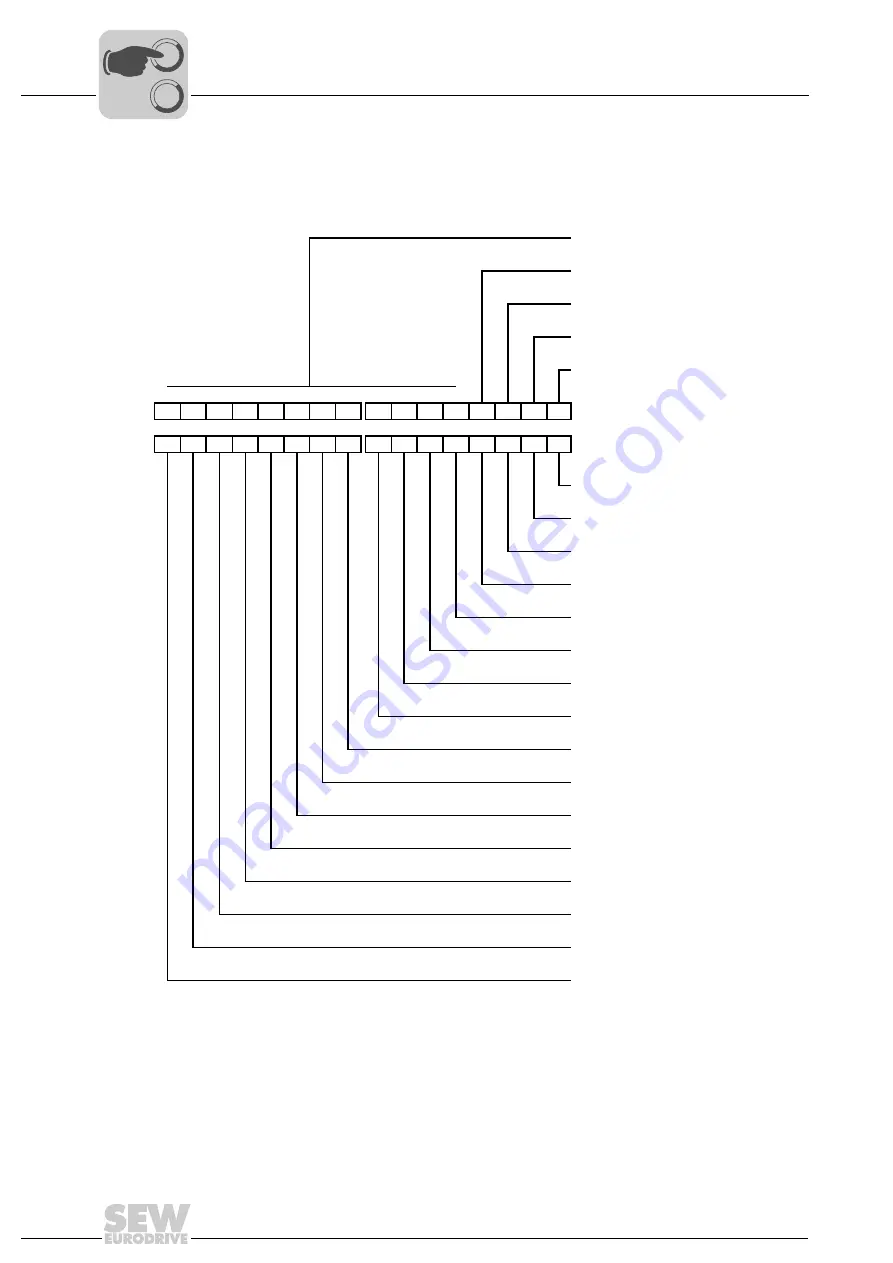
The following figure shows the assignment of the output and input data for the digital in-
puts/outputs (12 DI/4 DIO):
4 – 15: Reserved = 0
3: Binary output DO03
2: Binary output DO02
1: Binary output DO01
0: Binary output DO00
→
15 14 13 12 11 10
9
8
7
6
5
4
3
2
1
0
→
Master
MOVIPRO
®
←
15 14 13 12 11 10
9
8
7
6
5
4
3
2
1
0
←
0: Binary input DI00 / status of binary
output DO00
1: Binary input DI01 / status of binary
output DO01
2: Binary input DI02 / status of binary
output DO02
3: Binary input DI03 / status of binary
output DO03
4: Binary input DI04
5: Binary input DI05
6: Binary input DI06
7: Binary input DI07
8: Binary input DI08
9: Binary input DI09
10: Binary input DI10
11: Binary input DI11
12: Binary input DI12
13: Binary input DI13
14: Binary input DI14
15: Binary input DI15
0
0
I


