13
Technical data
Encoder interface
Manual – MOVISAFE
®
CS..A Safety Card (Version 2)
127
13.3
Encoder interface
Designation
Value/description
Features
Encoder interface for HTL encoder interfaces A, A, B, B,
sin/cos encoder signals
Permitted safety encoders
EI7C FS, AK0H, AK1H, E.7S, A.7W
Signal level
0 V – +3 V
Encoder track LOW (logic "0")
Encoder track HIGH (logic "1")
Maximum operating speed
EI7C FS, E.7S, A.7W
3600 min
-1
Maximum operating speed
AK0H, AK1H
6000 min
-1
Max. permitted input fre-
quency
1520 Hz
Response time of speed
measurement
Calculation formula:
Response time of speed measurement in ms = 13 +
7500/n
[n] = min
−1
Error response time of
speed measurement
1)
No greater than the response time without error.
1) The fault response time is the total time from when an internal error occurs or an external error in the en-
coder circuit is detected until the safe state triggered by the safety card.
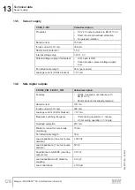
13.4
Safe digital inputs
F-DI00 – F-DI03
Value/description
Properties
DC 24 V input pursuant to EN 61131-2, type 3
Signal level
•
Logic "0" = LOW input:
≤ 5 V or ≤ 1.5 mA
•
Logic "1" = HIGH input:
≥ 11 V and ≥ 2 mA
Reference ground
GND
Power demand (typical)
0.21 W at DC 24 V
Input current
≤ 15 mA
Input resistance
≤ 4 kΩ at DC 24 V
Input filter time, parameterizable
4 ms – 250 ms
Permitted cable length
30 m
Error response time with single-pole
connection
No greater than the response time without
error.
Edge steepness of input signal
> 120 V/s
Input capacitance
< 500 pF
28482271/EN – 03/2019


