7
Electrical installation
Safe digital outputs (F-DO.)
Manual – MOVISAFE
®
CS..A Safety Card (Version 2)
60
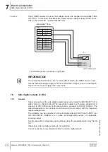
Variant 2
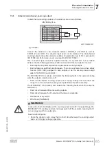
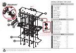
If only OSSD sensors are used, the voltage can also be supplied via terminals F-SS0
and F-SS1. In this case, deactivate the pulsed sensor voltage supply (F-SS0 and F-
SS1) in the "Assist CS.." parameterization tool.
[1]
9
10
3, 4, 7, 8
F-SS0
F-DI00
F-DI01
F-DI02
F-DI03
F-SS1
GND
0
5
2
6
X60
X60
MOVISAFE
®
CS..A
OSSD1
OSSD2
+24V
0V
9007207666494347
[1] OSSD sensor (e.g. scanner or light grid)
INFORMATION
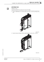
The achievable Performance Level is mainly determined by the OSSD sensors used.
Use the external voltage supply for sensors that have a higher current consumption
than the F-SS. sensor supply lines can provide.
7.6
Safe digital outputs (F-DO.)
7.6.1
General
Signal processing of the safe digital outputs takes place inside the MOVISAFE
®
CS..A
safety card in 2-channel format. The safe digital outputs can therefore achieve SIL 3
pursuant to IEC 61508 and Performance Level e pursuant to EN ISO 13849-1. The
external actuators to be connected and their wiring must comply with the respective
required safety class.
The actuators can be connected to the safe digital outputs F-DO00 and F-DO01 (not
with MOVISAFE
®
CSB21A) via 2 poles, sourcing/sinking output, or single-pole,
sourcing output.
Set the respective configuration during startup using the parameterization tool "Assist
CS..".
Single-pole, sinking digital outputs are not permitted.
It is not necessary to use shielded cables for all safe digital outputs.
28482271/EN – 03/2019


