background image

5

Single-point synchronization

Startup

Product Manual – MOVITRANS

®

 TES31A Decentralized Supply Unit Synchronization

42

5.5.2

Requirements

You have installed the unit correctly both mechanically and electrically.

The system and connected drives must be configured correctly.

Safety measures prevent accidental drive startup.

Safety measures prevent danger to persons or machines.

5.5.3

General

INFORMATION

You can find detailed project planning information in the MOVITRANS

®

 Project Plan-

ning and Planning manuals.

Correct project planning and installation are the prerequisites for successful startup.

29190657/EN – 04/2020

Summary of Contents for MOVITRANS TES31A

Page 1: ...57_0420 Drive Technology Drive Automation System Integration Services Product Manual Contactless Energy Transfer System MOVITRANS TES31A Decentralized Supply Unit Synchronization Edition 04 2020 29190...

Page 2: ...SEW EURODRIVE Driving the world...

Page 3: ...9 Protective separation 11 2 10 Startup operation 11 3 System description 12 3 1 Other applicable documentation 12 3 2 Multi point synchronization 12 3 3 Single point synchronization 13 3 4 System adv...

Page 4: ...r section 56 6 6 X5102_2 Digital outputs power section 58 6 7 X5121 MOVITRANS synchronization signal 59 6 8 X5122 MOVITRANS synchronization signal 62 6 9 X5161 Device interface for dual channel discon...

Page 5: ...1 3 Structure of the safety notes 1 3 1 Meaning of signal words The following table shows the grading and meaning of the signal words for safety notes Signal word Meaning Consequences if disregarded...

Page 6: ...f the hazard symbols The hazard symbols in the safety notes have the following meaning Hazard symbol Meaning General hazard Warning of automatic restart 1 3 4 Structure of embedded safety notes Embedd...

Page 7: ...demarks The brands and product names in this documentation are trademarks or registered trademarks of their respective titleholders 1 7 Copyright notice 2020 SEW EURODRIVE All rights reserved Unauthor...

Page 8: ...on Startup Maintenance and repairs Shutdown Disassembly Ensure that the persons who work on the product pay attention to the following regula tions conditions documentation and information National an...

Page 9: ...d devices systems and circuits in accordance with the standards of safety technology Instructed persons All work in the areas of transportation storage operation and waste disposal must be carried out...

Page 10: ...that the product is not subject to mechanical impact If necessary use suitable sufficiently dimensioned handling equipment Observe the information on climatic conditions in chapter Technical data of t...

Page 11: ...ations are increased temperatures noise or vibration for example Determine the cause Contact SEW EURODRIVE if necessary When the device is switched on dangerous voltages are present at all power conne...

Page 12: ...tructions Observe the applicable safety notes in these documents 3 2 Multi point synchronization The multi point synchronization function allows the user to synchronize separate line cable routes with...

Page 13: ...ster detects another syn chronization signal it performs the set Sync timeout response fault response Note the following There is only one master in the synchronization network All synchronization sta...

Page 14: ...function 5 X5122 MOVITRANS synchronization signal input 6 X5121 MOVITRANS synchronization signal output 7 X4108 CAN system bus input system bus 1 8 X4101 CAN system bus output system bus 1 9 X1201 AC...

Page 15: ...gth permitted for SBus communications depends on the set SBus baud rate SBus baud rate Total cable length 125 kBd 500 m 250 kBd 250 m 500 kBd standard 100 m 1000 kBd 25 m The following figure shows th...

Page 16: ...is necessary to connect the synchronization sig nals The following figure shows the installation diagram for the synchronization TES31 Master X5122 X5121 TES31 Slave 1 X5122 X5121 TES31 Slave N X5122...

Page 17: ...entation is drawn up for users that are familiar with and have basic knowledge of drive project planning 4 1 2 PC and software The Multi point synchronization function is part of the unit firmware You...

Page 18: ...centralized Supply Unit Synchronization 18 4 2 Connection of a TES31A decentralized supply unit 4 2 1 Overview Master Slave 1 Slave N 4 Input 400V AC Input 400V AC 1 2 3 Input 400V AC 31170183947 1 CA...

Page 19: ...e to property if the unit network is released inde pendently Fatal or severe injuries and damage to property can occur Before startup make sure that the line cable is not energized and there are no im...

Page 20: ...measures prevent danger to persons or machines 4 3 3 General INFORMATION You can find detailed project planning information in the MOVITRANS Project Plan ning and Planning manuals Correct project plan...

Page 21: ...t supply system to slave Configure the SBus address Startup completed Set up necessary cabling for network units Disconnect unit interface X5161 Switch on supply system of designated master Configure...

Page 22: ...ng up a master INFORMATION If the control signal source of the master is set to Terminals the synchronization stations are enabled after the line voltage is applied Observe the information in chapter...

Page 23: ...ation lost sync signal invalid may occur in other synchronization stations Reset this fault with a manual reset in the Setup window or with the process data control word Proceed as follows if you woul...

Page 24: ...pective line cable systems The setting 180 reverses the current direction IL t 0 90 180 270 360 180 in degrees 9007199598157451 A phase shift of 180 is useful if The current direction is reversed at j...

Page 25: ...ation 25 4 4 Operation 4 4 1 General The supply units synchronized in multi point mode can be controlled independently of each other and operated according to their set operating mode For further info...

Page 26: ...e point synchronization function is part of the unit firmware You will need the SEW EURODRIVE software MOVITOOLS MotionStudio for configuring the sup ply units 5 1 3 Supply unit The Single point synch...

Page 27: ...resulting line cable current must not exceed 85 A Set the setpoint input in the master to 94 to provide a resulting line cable cur rent of 85 A and to limit the load current per station to approx 28...

Page 28: ...cked 8461 210D 0 Setpoint source Master All sources except for SBus2 can be set Slave Setting blocked 8462 210E 0 Control signal source Master All sources except for SBus2 can be set Slave Setting blo...

Page 29: ...as an SP slave after the factory setting The desired setting must therefore be adjusted accordingly 10233 27F9 1 Frequency mode Setting blocked 10422 28B6 1 Sync phase angle Setting range restricted t...

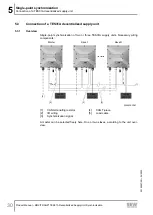
Page 30: ...ly unit 5 3 1 Overview Single point synchronization of two or three TES31A supply units Necessary wiring components Master Slave 1 Slave N Input 400V AC Input 400V AC Input 400V AC 2 1 3 4 5 309033570...

Page 31: ...ignal diagram of digital inputs outputs with external terminal enable and status request If the enable is implemented via an external terminal signal an external terminal signal may be connected at in...

Page 32: ...of the wiring in the com pensation box MOVITRANS Compensation Box TCS31A 5 4 1 Connecting line cables to two supply units When you are synchronizing two TES31A decentralized supply units both the load...

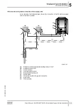
Page 33: ...igure shows the connection of the PE with two supply units connected in parallel 7 B TES 5 1 2 3 X2337 X1201 TES TCS 4 4 5 X2337 X1201 6 6 A A B 31554412811 A Protective earth equipotential bonding ca...

Page 34: ...esulting line cable current of 85 A The three load cables from the three supply units are merged into two load cables in the connection distributor The following components are included in the scope o...

Page 35: ...35 The following figure shows the topology at the highest expansion level with three sup ply units TCS10 TCS31A TVS10A TES31 Slave 1 TES31 Master X2337 X2337 TES31 Slave 2 X2337 IL IL IL 3 x IL 1 2 3...

Page 36: ...with three supply units connected in parallel 4 7 B TES 5 1 2 3 X2337 X1201 TES TES TVS TCS 4 4 5 5 X2337 X1201 X2337 X1201 6 6 6 A B C A A B 6 6 31279689611 A Protective earth equipotential bonding c...

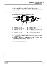
Page 37: ...8 7 1 2 3 4 5 6 31344529419 1 EMC screw fitting M25 5 EMC screw fitting M32 2 Screw plug made of metal 6 EMC screw fitting M32 3 EMC screw fitting M25 7 Terminal block in delivery state with four jump...

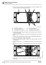
Page 38: ...e accessories pack on the two PE connection points M6 7 Route the three PE conductors on the internal PE connection 1 of the housing M5 8 Route the load cable prefabricated with cable lugs through the...

Page 39: ...Decentralized Supply Unit Synchronization 39 The following figure shows how the individual cores are positioned inside the connec tion distributor 1 3 2 4 1 3 2 4 1 3 2 4 TES 3 TES 2 TES 1 TCS31A 1 3...

Page 40: ...nit Synchronization 40 The following figure shows the connection diagram for the connection distributor TLS 1 TLS 2 PE PE PE 2 1 4 3 PE 2 1 4 3 PE PE PE 2 1 4 3 PE 2 1 4 3 1 2 3 4 2 1 4 3 PE 313504381...

Page 41: ...ge to property if the unit network is released inde pendently Fatal or severe injuries and damage to property can occur Before startup make sure that the line cable is not energized and there are no i...

Page 42: ...y The system and connected drives must be configured correctly Safety measures prevent accidental drive startup Safety measures prevent danger to persons or machines 5 5 3 General INFORMATION You can...

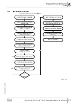
Page 43: ...s Switch off power to network Switch on the supply system Startup completed Set up necessary cabling for network units Disconnect the connections X5161 and X2337 Switch on supply system of designated...

Page 44: ...ting up a master INFORMATION If the control signal source of the master is set to Terminals the synchronization stations are enabled after the line voltage is applied Observe the information in chapte...

Page 45: ...chronization lost sync signal invalid may occur in other synchronization stations Reset this fault with a manual reset in the Setup node or with the process data control word Proceed as follows if you...

Page 46: ...nsation The following figure shows the compensation range to be observed in single point synchronization 31169746571 The shown standardized compensation range indicates the correct range regardless of...

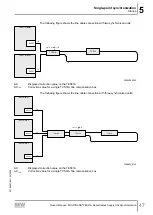
Page 47: ...X TCS 1 2 X X 30903363339 X Displayed correction value on the TES31A XTCS Correction value for a single TCS31A fine compensation box The following figure shows the line cable connection with three syn...

Page 48: ...iscover a difference in the active power between the synchronization sta tions correct it 3 Begin with the slave with the largest discrepancy and observe the Active power parameter 4 Select the Synchr...

Page 49: ...5 6 1 Enabling the network The master manages the enable control of the network If the master receives the en able signal all the synchronization stations switch from the status Disabled to the status...

Page 50: ...master is transmitted to the slaves The slaves then display the setpoint under Active setpoint in the Process val ues window Proceed as follows when synchronizing three stations 1 CAUTION Exceeded nom...

Page 51: ...ending on the status of the individual synchronization stations in their roles as master or slave The terminology for the various statuses is used in accordance with the texts in MOVITOOLS MotionStudi...

Page 52: ...in chapter 8 3 Fault reset The master for wards a reset via edge change to all the slaves Other re set types must be performed on the respective station When resetting a station refer to the informati...

Page 53: ...es depend on the device design and the components to be connected This is why you do not need all listed cables 6 3 Cable structure 6 3 1 Diagram The following table shows the cable structure based on...

Page 54: ...SI Output stage inhibit PE PE PE connection INFORMATION Pins 11 and 12 must be jumpered to enable the output stage The SEW EURODRIVE cable that is configurable in length comes equipped with this jumpe...

Page 55: ...esign 5G6 Han Q 4 2 male cable lug 5 x M6 Variable length TES TVS10A This connection cable cable lug 5 M6 is required for synchronizing 3 decentralized supply units in combination with a TVS10A connec...

Page 56: ...5 No Name Function 1 24V DC 24 V output 2 DI01 Data reception direction 01 3 0V24 0V24 reference potential 4 DI00 Data reception direction 00 with fixed assignment output stage inhibit 5 FE Equipoten...

Page 57: ...r section Product Manual MOVITRANS TES31A Decentralized Supply Unit Synchronization 57 Cable Length installation type Component 1 5 m Part number 19166214 3 m Part number 19166206 Cable design 5X0 34...

Page 58: ...4V DC 24 V output 2 DO01 Digital output nm 01 3 0V24 0V24 reference potential 4 DO00 Digital output nm 00 5 FE Equipotential bonding functional earth 6 6 1 Connection cable Cable Length installation t...

Page 59: ...cted here you must terminate the bus with a 120 resis tor Function Synchronization signal MOVITRANS output Connection type M12 5 pin female A coded Connection diagram 1 4 3 2 5 No Name Function 1 FE C...

Page 60: ...art number 13286358 15 m Part number 13286366 Custom lengths 1 5 m Part number 13286293 2 5 m Part number 13286307 Cable design 1X2X0 2 1X2X0 32 1X0 32 M12 male A coded M12 female A coded Fixed length...

Page 61: ...ual MOVITRANS TES31A Decentralized Supply Unit Synchronization 61 Conductor assignment Part number Signal name Color coding 13281348 13281356 13281364 13281372 13281380 13281399 13281402 13281410 1328...

Page 62: ...onnected here you must terminate the bus with a 120 resis tor Function Synchronization signal MOVITRANS input Connection type M12 5 pin male A coded Connection diagram 2 1 5 4 3 No Name Function 1 FE...

Page 63: ...rt number 13286358 15 m Part number 13286366 Custom lengths 1 5 m Part number 13286293 2 5 m Part number 13286307 Cable design 1X2X0 2 1X2X0 32 1X0 32 M12 female A coded M12 male A coded Fixed length...

Page 64: ...rface for dual channel disconnection input Function Input for dual channel disconnection of the power section output stage inhibit Connection type M12 5 pin female A coded Wiring diagram 1 4 3 2 5 No...

Page 65: ...a network If it is necessary to exchange an individual supply unit in a network e g due to a fault proceed as follows 1 DANGER Live product parts and power connections Severe or fatal injuries Do not...

Page 66: ...materials are hazardous to health and the environment These materials must be collected and disposed of separately Oil and grease Collect used oil and grease separately according to type Ensure that...

Page 67: ...otes 6 Enabling Network 49 F Fault information 52 Functional safety technology Safety note 10 H Hazard symbols Meaning 6 Synchronization 34 N Notes Designation in the documentation 5 Meaning of the ha...

Page 68: ...m Block diagram 31 External terminal enable and status enable 31 Signal words in safety notes 5 Startup 19 41 Compensation 46 General 20 42 Procedure 21 43 Safety note 11 Sync phase angle 24 Sync time...

Page 69: ......

Page 70: ......

Page 71: ......

Page 72: ...SEW EURODRIVE Driving the world SEW EURODRIVE GmbH Co KG Ernst Blickle Str 42 76646 BRUCHSAL GERMANY Tel 49 7251 75 0 Fax 49 7251 75 1970 sew sew eurodrive com www sew eurodrive com...

Reviews: