Manual – Data Matrix Positioning System PCV80A-F200-R4-V19-SEW
17
4
Mounting the read head
Installation
4.2.2
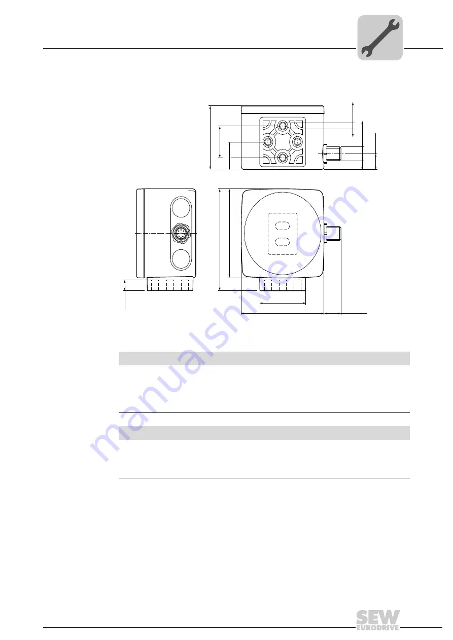
Dimension drawing for the read head
All dimensions in mm (in)
8069384459
7
1
2
3
4 5
6
8
70 (2.8)
80 (3.2)
38.5 (1.5)
70 (2.8)
14.5 (0.6)
1
2
22
(0.9)
51 (2)
ø 25 (1)
12
(0.5)
M12 x 1
9 (0.4)
4 x M6
NOTICE
Using longer retaining screws.
Damage to the read head.
Select the length of the retaining screws in such a way that the maximum insertion
depth of the screws in the threaded inserts of the read head is 8 mm (0.3 in).
NOTICE
Tightening the screws with excessively high torque.
Damage to the read head.
The maximum torque of the retaining screws must not exceed 9 Nm.


