-5-
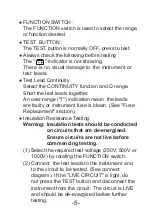
● FUNCTION SWITCH :
The FUNCTION switch is used to select the range,
or function desired.
● TEST BUTTON :
The TEST button is normally OFF, press to test.
● Always check the following before testing :
The " " indicator is not showing.
There is no visual damage to the instrument or
test leads.
● Test Lead Continuity
Select the CONTINUITY function and Ω range.
Short the test leads together.
An over-range ("1") indication mean the leads
are faulty or instrument fuse is blown. (See "Fuse
Replacement" section).
● Insulation Resistance Testing:
Warning: Insulation tests should be conducted
on circuits that are de-energised.
Ensure circuits are not live before
commencing testing.
(1) Select the required test voltage (250V, 500V or
1000V) by rotating the FUNCTION switch.
(2) Connect the test leads to the instrument and
to the circuit to be tested. (See connect
diagram). If the "LIVE CIRCUIT" is light, do
not press the TEST button and disconnect the
instrument from the circuit. The circuit is LIVE
and should be de-energised before further
testing.


