background image

Medidores de aislamiento - Megohmetros Digitales VDC GigaOhmios 6213-IN SEW manual ingles www.viaindustrial.com


Medidores de aislamiento - Megohmetros Digitales VDC GigaOhmios 6213-IN SEW manual ingles www.viaindustrial.com


The


Ener-Save


mode


saves


battery


life


by


automatically


The


Ener-Save


mode


is


the


default


mode


of


the


instrument.


The


Ener-Save


mode


is


enabled


when


pressing


the


TEST


button


The


Ener-Save


mode


is


disabled


when


pressing


the


TEST


button


When


Ener-Save


mode


is


disabled,


the


instrument


operates


in


6.


FUNCTIONS


(see


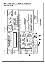
FRONT


PANEL


LAYOUT).


6.1


Power-On


To


switch


your


instrument


on,


press


the


"ON"


button


(


1


).


The


L.C.D.


will


display


the


model


number.


Follow


interactive


instructions


on


L.C.D..


6.2


Insulation


Resistance


Measurement


@


10kVdc

.


To


Select


10KVdc


test


voltage,


press


10KV


button


(


2


).


6.3


Insulation


Resistance


Measurement


@


5KVdc

.


To


Select


5KVdc


test


voltage,


press


5KV


button


(


4


).


6.4


Insulation


Resistance


Measurement


@


2.5KVdc

.


To


Select


2.5KVdc


test


voltage,


press


2.5KV


button


(


5


).


6.5


Insulation


Resistance


Measurement


@


1KVdc

.


To


Select


1KVdc


test


voltage,


press


1KV


button


(


6


).


6.6


Insulation


Resistance


Measurement


@


Multiple


of


500Vdc


adjustment


To


add


500Vdc


to


the


selected


test


voltage,


press


+500V


button


(


7


).


To


subtract


500Vdc


to


the


selected


test


voltage,


press


-500V


button


(


8


).


6.7


Ener-Save

TM


mode.


TM


turning


the


instrument


to


low


consumption


(reducing


the


test


duration


).


TM


TM


(


3


)


for


less


than


3


Seconds


.


TM


(


3


)


for


more


than


3


seconds.


TM


continuous


mode


(up


to


10


minutes)


.


6.8


Voltage


Output


Bar-Graph

.


The


bar-graph


shows


the


voltage


present


on


the


leads.


It


also


shows


the


voltage


charging


a


cable


or


capacitive


system


under


test


and


shows


the


decay


during


the


automatic


capacitive


discharge


of


the


system


under


test.


-13-

Summary of Contents for 6213A-IN

Page 1: ...itales VDC GigaOhmios 6213 IN SEW manual ingles www viaindustrial com Medidores de aislamiento Megohmetros Digitales VDC GigaOhmios 6213 IN SEW manual ingles www viaindustrial com 6213A IN DIGITAL VAR...

Page 2: ...ingles www viaindustrial com TABLE OF CONTENTS Index 2 Front Panel Layout 3 Inside Lid Instructions 4 Safety precautions 5 8 Overview 9 Features 10 Connections 11 Specifications 12 Functions 13 15 Sp...

Page 3: ...AYSREADUSER SMANUALBEFOREOPERATINGTHISINSTRUMENT Useonlyonde energisedandisolated disconnectedsystem DONOTPROCEEDIFVOLTAGEPRESENT Checktestleadsfordefects Ifanycracksordamages replacewithnewtest leads...

Page 4: ...AR WARNING Thisinstrumentshould notbeusedinexplosive orinflammable environments although thereisunlikelytobea firehazardfromthe instrumentitself However arcingin faultyinsulation sparkingcausedwhen ma...

Page 5: ...or test leads Preparations for testing of power system grounding or close to it can leave personnel vulnerable to exposure caused by faults at or fed from the system under test transferred potentials...

Page 6: ...hey were new Always disconnect the test leads when changing the batteries by removing the cover which give access to the batteries Always double check the lead connections before making any measuremen...

Page 7: ...warning features should your Variable High Voltage Digital Insulation Meter be connected to a live system 1 3 Never open your Variable High Voltage Digital Insulation Meter except for battery replacem...

Page 8: ...gaOhmios 6213 IN SEW manual ingles www viaindustrial com 1 7 Your Variable High Voltage Digital Insulation Meter has a live circuit warning beeper If It is connected to a live circuit a rapid pulsatin...

Page 9: ...his bar graph is showing voltage output during the first 30 seconds of the test or during automatic discharge of circuits During the automatic discharge of the circuit tested the bar graph displays th...

Page 10: ...6 5KV 7KV 7 5KV 8KV 8 5KV 9KV 9 5KV 10KV Calculate Dielectric Absorption Ratio DAR Automatically Calculate Polarization Index PI Automatically Insulation resistance Auto Ranging on all ranges TM Bar g...

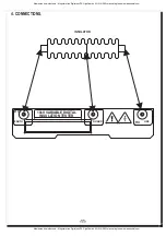
Page 11: ...Ohmios 6213 IN SEW manual ingles www viaindustrial com Medidores de aislamiento Megohmetros Digitales VDC GigaOhmios 6213 IN SEW manual ingles www viaindustrial com 4 CONNECTIONS INSULATOR HV 10kV VAR...

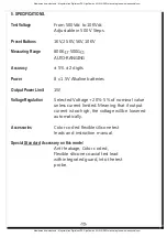
Page 12: ...5KV 5KV 10KV Measuring Range 800K 500G AUTO RANGING Accuracy 5 2 digits Power 8 x 1 5V Alkaline batteries Output Power Limit 1W Voltage Regulation Selected Voltage 20 5 of nominal value unless curren...

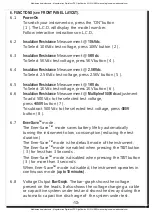
Page 13: ...test voltage press 10KV button 2 6 3 Insulation Resistance Measurement 5KVdc To Select 5KVdc test voltage press 5KV button 4 6 4 Insulation Resistance Measurement 2 5KVdc To Select 2 5KVdc test volta...

Page 14: ...certain time or to make comparison See Special Features for more Timer Functions 6 11 STOP test To stop the test in progress press the TEST button 3 The test will immediately stop discharge and the i...

Page 15: ...ed by a one second long beep accompanied by the HOLD message on the display DO NOT REMOVE LEADS UNTIL THE HOLD MESSAGE APPEARS ON THE DISPLAY 6 15 Replace Battery Warning Indicator If the battery ener...

Page 16: ...Polarization Index The Polarization Index or PI is the ratio of the Insulation Resistance measured at 10 Minutes divided per the Insulation Resistance measured at 1 Minute 10 Minutes after starting a...

Page 17: ...t any time before during and after the test It s your responsibility to ensure proper contact of the leads at all times Once a test is finished the testers will automatically discharge capacitive or i...

Page 18: ...6213 IN SEW manual ingles www viaindustrial com 8 PREPARATION FOR MEASUREMENT 8 1 Before testing always check the following At Power ON read the display to make sure the Replace Battery message is no...

Page 19: ...ng care to observe correct polarity Replace battery cover 9 2 Cleaning Storage Periodically wipe the case with a damp cloth and detergent Do not use abrasives or solvents If the meter is not to be use...

Page 20: ...are not live before commencing testing Secure both test leads properly to the insulation to test and use guard lead to collect surface leakage Good contacts are necessary to avoid flashing at high vol...

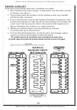
Page 21: ...surface of the insulator is too high and therefore the insulator may require cleaning 4 Should your insulator require cleaning follow the procedures recommended by it s manufacturer 5 For Final Test a...

Page 22: ...r characteristics may deteriorate due to many factors Their material properties may deteriorate with time and frequency use as well as stress put on to them One of the factor we will be testing is the...

Page 23: ...ormers are painted or dipped with insulating varnish large power transformers are painted with High Voltage insulating paint of very high specifications Many Applications uses insulating material to p...

Page 24: ...arranty does not apply to any of our products which have been repaired or altered by unauthorized persons in any way so as in our sole judgement to injure their stability or reliability or which have...

Reviews: