12
Manual – DFD11B DeviceNet Fieldbus Interface
4
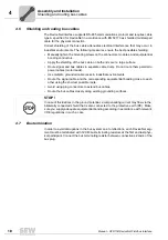
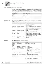
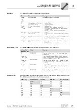
Installing the DFD11B option card in MOVITRAC® B
Assembly and Installation
4.2
Installing the DFD11B option card in MOVITRAC
®
B
4.2.1
System bus connection between a MOVITRAC
®
B and the DFD11B option
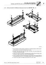
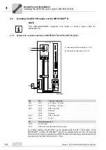
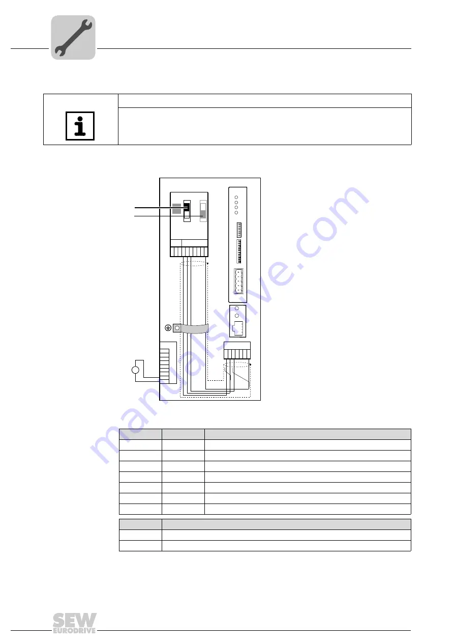
To simplify cabling, the DFD11B can be supplied with DC 24 V from X46.7 of the
MOVITRAC
®
to X26.7. MOVITRAC
®
B must be supplied with DC 24 V at terminals
X12.8 and X12.9 when it supplies the DFD11B option. Activate the system bus terminat-
ing resistor at the FSC11B option (S1 = ON).
NOTE
Only SEW-EURODRIVE engineers may install or remove option cards for
MOVITRAC
®
B.
62198AXX
[1] Terminating resistor activated, S1 = ON
[2] DIP switch S2 (reserved), S2 = OFF
X46
X26
Terminal assignment
X46:1
X26:1
SC11 SBus +, CAN high
X46:2
X26:2
SC12 SBus –, CAN low
X46:3
X26:3
GND, CAN GND
X26:4
Reserved
X26:5
Reserved
X46:6
X26:6
GND, CAN GND
X46:7
X26:7
DC 24 V
X12
Terminal assignment
X12:8
DC 24 V input
X12:9
GND reference potential for the binary inputs
X45
X46
1 2 3 4 5 6
H L
⊥
FSC11B
MOVITRAC
®
B
S1
OFF
ON
7
S2
X44
X26
1 2 3 4 5 6 7
X24
H1
H2
X12
1
2
3
4
5
6
7
8
24V IO
24V
–
+
9
GND
=
[1]
DFD 11B
MOD/
NET
BUS-
FAULT
0
1
PIO
NA(5)
NA(4)
NA(3)
NA(2)
NA(1)
DR(1)
DR(0)
PD(4)
PD(3)
PD(2)
PD(1)
PD(0)
AS
F2
F1
1
2
3
4
5
NA(0)
S1
S2
X30
BIO
[2]


