Manual – DFD11B DeviceNet Fieldbus Interface
15
4
Installing the DFE11B / UOH11B gateway
Assembly and Installation
4.3
Installing the DFE11B / UOH11B gateway
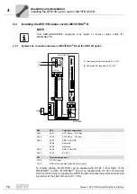
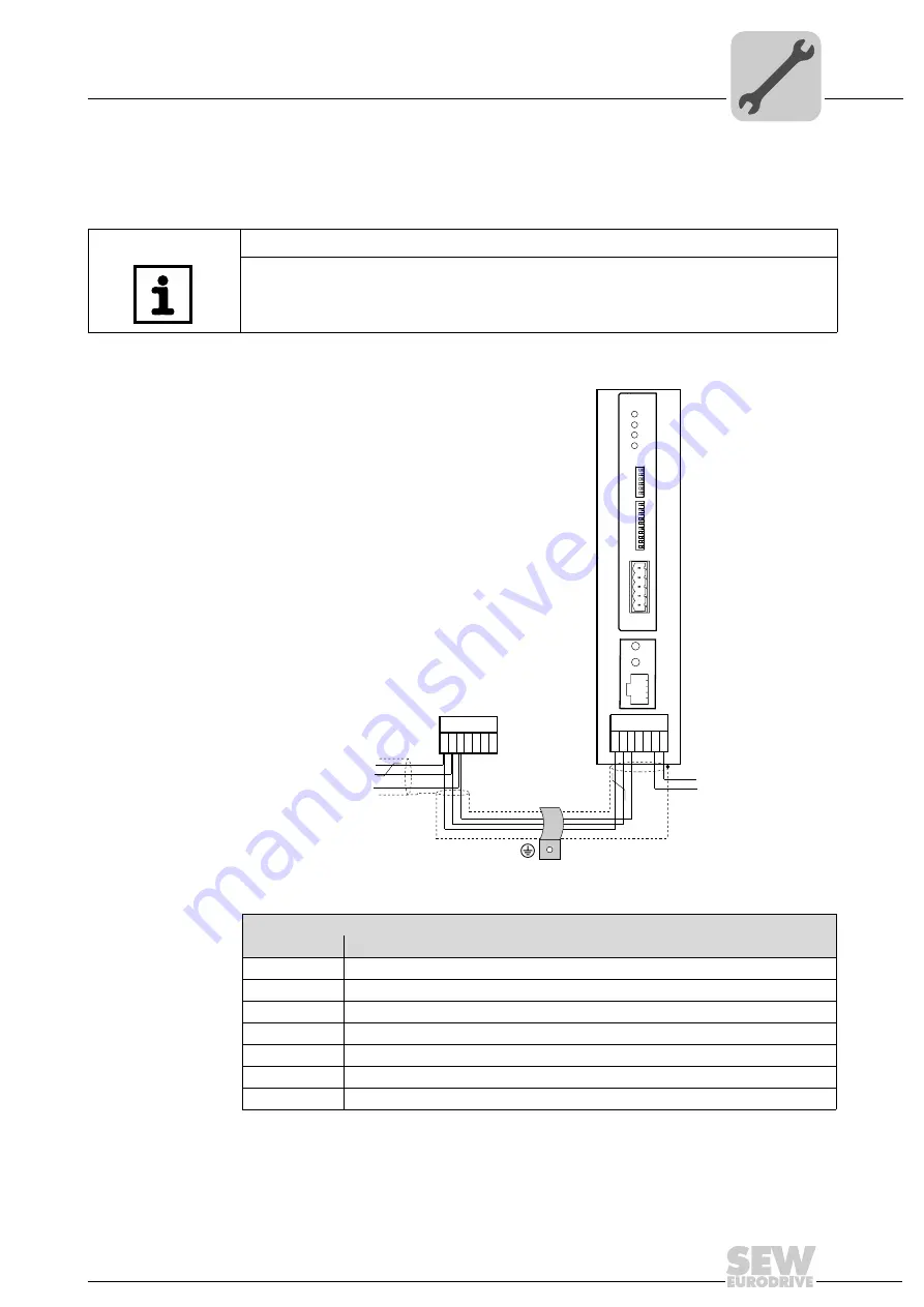
The following figure shows the connection of the DFD11B option via the UOH11B:X26
gateway housing.
The gateway housing has a power supply of DC 24 V that is connected to X26.
Connect the system bus terminating resistor at the end of the system bus connection.
NOTE
Only SEW-EURODRIVE engineers are allowed to install or remove option cards
in/from the UOH11B gateway housing.
62197AXX
UOH11B gateway housing
X26
Terminal assignment
X26:1
SC11 system bus +, CAN high
X26:2
SC12 system bus -, CAN low
X26:3
GND, CAN GND
X26:4
Reserved
X26:5
Reserved
X26:6
GND, CAN GND
X26:7
DC 24 V
X26
1 2 3 4 5 6 7
SEW Drive
UOH11B
DC+24 V
GND
X24
H1
H2
SC11 Sys, CAN high
SC12 Systembus -, CAN low
GND, CAN GND
DFD 11B
MOD/
NET
BUS-
FAULT
0
1
PIO
NA(5)
NA(4)
NA(3)
NA(2)
NA(1)
DR(1)
DR(0)
PD(4)
PD(3)
PD(2)
PD(1)
PD(0)
AS
F2
F1
1
2
3
4
5
NA(0)
S1
S2
X30
BIO


