Manual – DFD11B DeviceNet Fieldbus Interface
17
4
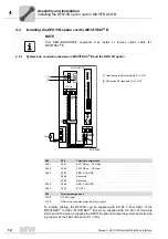
Pin assignment
Assembly and Installation
4.5
Pin assignment
The assignment of connecting terminals is described in the DeviceNet specification
(Volume I, Appendix A).
The DFD11B option card is opto-decoupled on the driver side in accordance with the
DeviceNet specification (Volume I, Chapter 9). This means the CAN bus driver must be
powered with 24 V voltage via the bus cable. The cable to be used is also described in
the DeviceNet specification (Volume I, Appendix B). The connection must be made ac-
cording to the color code specified in the following table.
DFD11B -
DeviceNet con-
nection
According to the DeviceNet Specification a linear bus structure without or with very short
droplines is required.
The maximum permitted cable length depends on the baud rate setting:
54075AXX
Pin no.
Signal
Meaning
Color coding
1
V–
0V24
BK
2
CAN_L
CAN_L
BU
3
DRAIN
DRAIN
blank
4
CAN_H
CAN_H
WH
5
V+
24 V
RD
DFD11B
1
2
3
4
5
DFD11B
X30
Baud rate
Maximum cable length
500 kBaud
100 m
250 kBaud
250 m
125 kBaud
500 m


