Manual – DFD11B DeviceNet Fieldbus Interface
47
5
Programming samples in RSLogix 500 for SLC 500
Project Planning and Startup
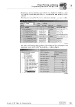
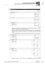
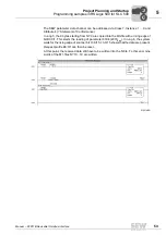
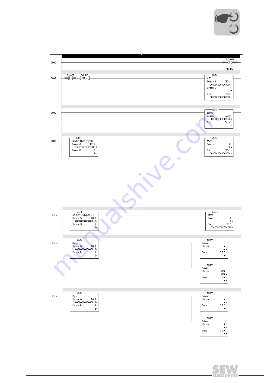
Output bit O:3.0/0 is set in rung 0 (program line 0), thereby starting DeviceNet commu-
nication (
→
description of the DeviceNet scanner).
Rungs 1 and 3 implement the status engine with which states 0... 3 are implemented.
The current status is written to the outputs O:1.0 of the output module of the SLC500 in
rung 2.
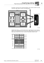
The process data values are output to the scanner memory area in the following figure.
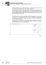
Status 0 is created in rung 4. In this status, a 6 (ENABLE) is written to memory area
01912AEN
Status engine for control of sense of rotation
Output of the status engine
If status > 3, change to status 0
Start DeviceNet communication
01913AEN
If status > 3, change to status 0
Status 0: Start motor, speed = 1000 rpm
Status 1: Stop motor
0
0
I

