48
Manual – DFD11B DeviceNet Fieldbus Interface
5
Programming samples in RSLogix 500 for SLC 500
Project Planning and Startup
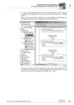
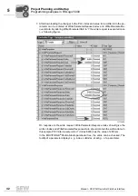
O:3.3 that represents process output data word 1. A 5000 is written to memory area
O:3.4 (process output data word 2), which represents 1000 rpm.
Status 1 is created in rung 5. In this status, a 0 (RAPID STOP) is written to memory area
O:3.3 that represents process output data word 1. A 0 is written to memory area O:3.4
(process output data word 2), which represents the value 0 rpm. This means the motor
is stopped with the rapid stop. States 2 and 3 are treated similarly to states 0 and 1, and
are thus not explained any further.
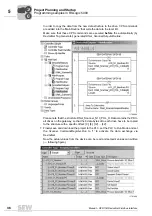
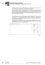
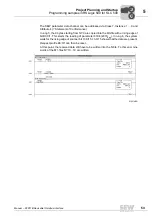
In the figure above, the current actual value of the device with address 8, which is locat-
ed in memory area I:3.6 (process input data word 2), is multiplied by a constant factor
(in this case, by 1) and written to output memory area O:3.7 (process output data word
2 of the device with address 0).
In addition, the value 6 (ENABLE) is written to the process output data word 1 of the de-
vice with address 0 (O:3.6). Thus, the device with address 0 follows the actual speed
with enable signal from the device with address 8.
01914AEN
Transmit actual position from motor 1 to motor 2
0
0
I


