background image

Manual – MOVI-PLC® advanced DHE41B/DHF41B/DHR41B Controller 

41

4

Installing the MOVI-PLC® advanced DHR41B controller

Mounting/Installation Instructions

4.5.8

Operating displays of the MOVI-PLC

®


advanced

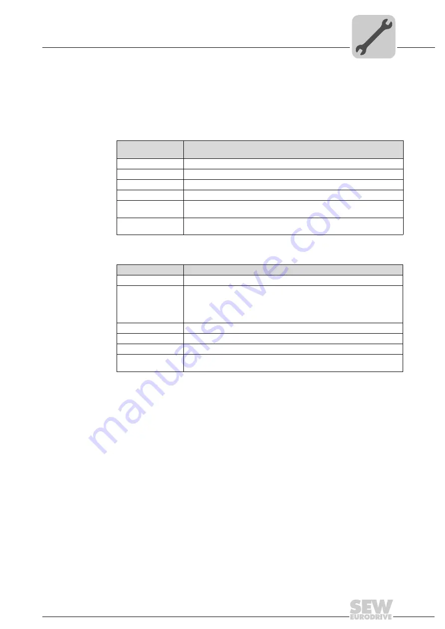
 DHR41B controller in EtherNet/IP mode

The LEDs L13 and L14 of the DHR41B indicate the current condition of the DHR41B
option and the EtherNet/IP system.

LED L13 (NET-
WORK STATUS)

LED 

L13 (NETWORK STATUS) 

indicates the status of the EtherNet/IP system.

LED L14 (MOD-
ULE STATUS)

LED 

L14 (MODULE STATUS)

 indicates that the bus electronics are operating correctly.

Status of the LED 
L13

Meaning

Off

The DHR41B option does not yet have any IP parameters.

Flashing green/red

The DHR41B option card performs an LED test.

Flashing green

There is no controlling IO connection.

Green

There is a controlling EtherNet/IP IO connection.

Red

A conflict while assigning the IP address was detected. Another station in the net-
work uses the same IP address.

Flashing red

The previously established controlling IO connection is in timeout status. The sta-
tus is reset by restarting communication.

Status of the LED L14 Meaning

Off

The DHR41B option card is not supplied with voltage or is defective

Flashing green

If the NETWORK STATUS LED is off at the same time, the TCP/IP stack of 
the DHR41B option card will be started. If this status continues  and DHCP is 
activated, the DHR41B option card waits for data from the DHCP server.

If the NETWORK STATUS LED is flashing green at the same time, the appli-
cation of the DHR41B option card is started.

Flashing green/red

The DHR41B option card performs an LED test.

Green

Indicates the standard operating state of the DHR41B option card

Red

The DHR41B option card is in fault state.

Flashing red 

A conflict while assigning the IP address was detected. Another station in the net-
work uses the same IP address.

Summary of Contents for DHE41B

Page 1: ...Drive Technology Drive Automation System Integration Services MOVI PLC advanced DHE41B DHF41B DHR41B Controller Manual Edition 04 2008 16623215 EN ...

Page 2: ...SEW EURODRIVE Driving the world ...

Page 3: ...net 1 system bus connector X36 20 4 3 6 Connection of the Ethernet 2 interface connector X37 20 4 3 7 Operating displays of the MOVI PLC advanced DHE41B controller 21 4 3 8 DIP switch S1 default IP address 23 4 3 9 SD memory card type OMH41B T 23 4 4 Installing the MOVI PLC advanced DHF41B controller 24 4 4 1 Function description of the terminals DIP switches and LEDs 24 4 4 2 PROFIBUS connection ...

Page 4: ...VI PLC advanced DH 41B controller 51 4 10 Shielding and routing bus cables 51 5 Project Planning and Startup 52 5 1 Configuration with the MOVITOOLS MotionStudio PC software 52 5 2 Configuration and startup of the drives 58 5 3 Configuration and startup in the PLC Editor 58 5 4 Replacing the unit 58 6 Error Diagnostics 59 6 1 Diagnostic procedure for system bus CAN 1 CAN 2 59 6 2 Diagnostic proced...

Page 5: ...le to persons responsible for the plant and its op eration as well as to persons who work independently on the device You must also ensure that the documentation is legible Symbol SIGNAL WORD Nature and source of hazard Possible consequence s if disregarded Measure s to avoid the hazard Symbol Signal word Meaning Consequences if disregarded Example General hazard Specific hazard e g electric shock...

Page 6: ...achieve the specified product characteristics and perfor mance requirements SEW EURODRIVE assumes no liability for injury to persons or damage to equipment or property resulting from non observance of these operating in structions In such cases any liability for defects is excluded 1 4 Copyright notice 2007 SEW EURODRIVE All rights reserved Any reproduction modification distribution or unintended ...

Page 7: ... The MOVIDRIVE MDX60B 61B drive inverters may not perform safety functions with out higher level safety systems Use higher level safety systems to ensure protection of equipment and personnel For safety applications ensure that the information in the fol lowing publications is observed Safe Disconnection for MOVIDRIVE MDX60B 61B 2 3 Hoist applications MOVIDRIVE MDX60B 61B MOVITRAC B and MOVIAXIS a...

Page 8: ...al MPLCMotion_MDX and MPLCMotion_MX Libraries for MOVI PLC manual MPLCMotion_MC07 and MPLCMotion_MM Libraries for MOVI PLC manual MOVIDRIVE MDX60 61B system manual MOVITRAC B system manual MOVIAXIS system folder The MOVI PLC Programming in the PLC Editor system manual contains instructions for IEC 61131 3 compliant MOVI PLC programming The library manuals describe the motion libraries for MOVI PLC...

Page 9: ...hnical Data Unit types The MOVI PLC advanced DH 41B is available in 3 variants which differ in the integrat ed fieldbus interfaces Engineering The engineering of the MOVI PLC advanced DH 41B controller includes the following activities Configuration Parameterization Programming These activities are carried out using the MOVITOOLS MotionStudio engineering soft ware The software has a number of usef...

Page 10: ...her actuators as well as evalu ating decentralized inputs and outputs In a stand alone topology operator terminals DOP11B function as the interface be tween the operator and machine You can connect MOVI PLC advanced DH 41B directly to the company s Ethernet net work 60544AXX Figure 1 Example of a topology when using MOVI PLC advanced DH 41B as the standalone control for a complete machine 1 Operat...

Page 11: ...er coordinates motion sequences in the axis system The controller is connected to a higher level PLC via the PROFIBUS interface or via one of the integrated fieldbus interfaces 58621AXX Figure 2 Example of a topology for controlling each machine module using a MOVI PLC advanced DH 41B controller 1 Higher level PLC 2 System bus CAN 1 CAN 2 3 MOVIMOT via fieldbus interface DeviceNet MFD connected di...

Page 12: ...e following advantages Less time required to start up the system Simple documentation of the application program as all important parameter data can be transferred from the program of the higher level controller Cyclical and acycli cal data exchange via PROFIBUS DP While process data is usually exchanged cyclically drive parameters are read or written acyclically using functions such as Read and W...

Page 13: ...nd outputs Binary inputs and outputs enable you to switch actuators e g valves and evaluate bi nary input signals e g sensors You can freely use the binary inputs and outputs in the PLC Editor of the MOVITOOLS MotionStudio software in programming Diagnostics The LEDs of the MOVI PLC advanced DH 41B controller indicate the following states Power supply of binary inputs and outputs General status of...

Page 14: ... appropriate measures to avoid electrostatic charges use discharge strap con ductive shoes etc before touching the MOVI PLC advanced DH 41B Before installing the MOVI PLC advanced DH 41B controller remove the keypad and the front cover After installing the MOVI PLC advanced DH 41B controller replace the keypad and the front cover Keep the MOVI PLC advanced DH 41B controller in its original packagi...

Page 15: ...m the slot do not twist 2 Remove the retaining screws of the black cover plate on the card retaining bracket Remove the black cover plate 3 Position the option card onto the retaining bracket so that the retaining screws fit into the corresponding bores on the card retaining bracket 4 Insert the retaining bracket with installed option card into the slot pressing slightly so it is seated properly S...

Page 16: ...t or output DIO 2 Binary input or output DIO 3 Binary input or output DIO 4 Binary input or output DIO 5 Binary input or output DIO 6 Binary input or output DIO 7 Terminal X34 RS485 interfaces COM1 COM2 plug in terminals X34 1 X34 2 X34 3 X34 4 X34 5 X34 6 RS RS insulated RS RS insulated DGND GND insulated Signal RS485 COM 1 Signal RS485 insulated COM 2 Signal RS485 COM 1 Signal RS485 insulated CO...

Page 17: ...r binary output All eight binary outputs can be operated simultaneously with this current To avoid the danger of maximum voltage peaks you may not connect inductive loads to the supply voltage or to the binary inputs or outputs without free wheeling diodes Cable specification Only connect cables with a minimum core cross section of 0 25 mm2 AWG23 and a maximal core cross section of 1 mm2 AWG18 IEC...

Page 18: ...CAN bus or DeviceNet cables NOTES The CAN 2 system bus is electrically isolated Therefore it is recommended to use the CAN 2 X32 interface for connecting field devices e g CANopen inputs and outputs The CAN 1 system bus is not electrically isolated Therefore it is recommended to use the CAN 1 X33 interface to connect inverters via the system bus in the control cabinet SEW EURODRIVE recommends conn...

Page 19: ...ace connector X34 You can connect one of the following devices to the RS485 interfaces COM1 2 connec tor X34 DOP11A operator terminals Gearmotor with integrated frequency inverter MOVIMOT STOP There must not be any potential displacement between the units connected via the CAN 2 system bus There must not be any potential displacement between the units connected via the CAN 1 system bus Take suitab...

Page 20: ... of the Ethernet 2 interface connector X37 You can connect an engineering PC to the Ethernet 2 interface connector X37 Using the Ethernet 2 interface the MOVI PLC advanced DHE41B controller can also exchange data via UDP TCP with another controller 61522AXX Figure 6 Example Connecting an engineering PC via the Ethernet 2 interface to X37 PC COM X35 X36 X37 2 4 6 1 3 5 X34 DHE41B 1 2 3 1 3 4 2 1 2 ...

Page 21: ...rrect the baud rate set for the CAN 1 system bus 3 Check and correct the terminating resistors of the CAN 1 system bus Flashing red 1 Hz Warning on the CAN 1 system bus 1 Check and correct the cabling of the CAN 1 system bus 2 Check and correct the baud rate set for the CAN 1 system bus Status of the LED L2 Diagnostics Troubleshooting Orange The CAN 2 system bus is being initial ized Green The CAN...

Page 22: ... see chapter SD memory card type OMH41B T 63437AXX State of the LEDs L6 L7 L8 L9 Diagnostics Troubleshooting Off No voltage present Green Voltage at LED n Red Voltage at LED m Orange Voltage at LED n and m X31 1 3 5 7 9 2 4 6 8 10 L6 L7 L8 L9 n m Status of the LED L10 Diagnostics Troubleshooting Green Voltage supply for the binary inputs outputs is OK Off Voltage supply for the binary inputs outpu...

Page 23: ...ent technology functions The technology level can be changed by replacing the SD memory card Variants Bootloader update When the LEDs L3 and L4 flash orange at a 1 Hz frequency after power on a bootloader update is required Proceed as follows Do not switch off the power supply during the entire process Press the reset button T1 on the front of the DH 41B option for 3 seconds When the bootloader up...

Page 24: ...tput DIO2 3 Status input or output DIO0 1 Status of voltage supply I O Reserved Reserved The two color LEDs 13 16 display the cur rent status of the fieldbus interface and the DeviceNet system Status of PROFIBUS bus electronics Status of PROFIBUS communication Terminal X30P PROFIBUS Sub D9 X30P 9 X30P 8 X30P 7 X30P 6 X30P 5 X30P 4 X30P 3 X30P 2 X30P 1 GND M5V RxD TxD N N C VP P5V 100 mA GND M5V CN...

Page 25: ... or output Binary input or output Binary input or output Binary input or output Binary input or output Terminal X34 RS485 interfaces COM1 COM2 plug in terminals color BK X34 1 X34 2 X34 3 X34 4 X34 5 X34 6 RS RS insulated RS RS insulated DGND GND insulated Signal RS485 COM 1 Signal RS485 insulated COM 2 Signal RS485 COM 1 Signal RS485 insulated COM 2 Reference potential COM 1 Reference potential C...

Page 26: ... components cannot communicate via the bus medium The PROFIBUS interface sends a TTL control signal for a repeater or fiber optic adapter reference pin 9 via pin 4 CNTR P Baud rates greater than 1 5 MBaud The MOVI PLC advanced DHF41B controller with baud rates 1 5 MBaud can only be operated with special 12 MBaud PROFIBUS connectors Bus terminator You do not need to equip the MOVI PLC advanced DHF4...

Page 27: ...m is in preparation Pin assignment The assignment of connecting terminals is described in the DeviceNet specification Volume I Appendix A The DHF41B option card is opto decoupled on the driver side in accordance with the DeviceNet specification Volume I Chapter 9 This means the CAN bus driver must be powered with 24 V voltage via the bus cable The cable to be used is also described in the DeviceNe...

Page 28: ...ave to switch the compact controller or the inverter in which the MOVI PLC advanced DHF41B controller is installed on and off again for the changes to take effect power 24 V off on Setting the baud rate The baud rate is set with DIP switches 26 and 27 4 4 4 Connecting SafetyBus connector X38 The connection to the SafetyBus bus system is in preparation 63210AXX The default setting for the station a...

Page 29: ... error pas sive state Red light BUS ERROR BusOff state The number of physical bus errors has increased despite a switch to the error passive state Access to the bus is switched off Yellow light POWER OFF External voltage supply has been turned off or is not con nected Status of the LED L14 Status Meaning Flashing green 125 ms cycle DUP MAC check Unit is performing DUP MAC check Off Not switched on...

Page 30: ...cycle Minor fault or connection tim eout Invalid baud rate set via DIP switches A correctable fault has occurred Polled I O connection is in timeout status Red light Critical fault or critical link failure An error that cannot be corrected has occurred BusOff DUP MAC check has detected an error Status of the LED L16 Status Meaning Off Not switched on OffLine Unit is off line Unit performs DUP MAC ...

Page 31: ...ables in the PROFI BUS network Flashing red 1 Hz The MOVI PLC advanced DHF41B con troller recognizes the baud rate but the DP master does not communicate with MOVI PLC advanced DHF41B The MOVI PLC advanced DHF41B con troller was either not configured in the DP master or it was configured incorrectly Check and correct the PROFIBUS station address set in the MOVI PLC advanced DHF41B con troller and ...

Page 32: ...hernet 4 RJ45 socket X30 2 DIP switches 20 21 20 21 ON OFF ON OFF Default IP address 192 168 10 4 Stored IP address DHCP EtherNet IP Modbus TCP IP PROFINET Connector X38 SafetyBus plug in terminals X38 1 X38 2 X38 3 Reserved Reserved Reserved Terminal X31 Binary inputs and out puts plug in terminals color BK X31 1 X31 2 X31 3 X31 4 X31 5 X31 6 X31 7 X31 8 X31 9 X31 10 24 V input REF24V DIO 0 DIO 1...

Page 33: ...y isolated plug in terminals color YE BK X32 1 X32 2 X32 3 REF_CAN 2 CAN 2H CAN 2L Reference potential for system bus CAN 2 System bus CAN 2 high System bus CAN 2 low Terminal X33 System bus CAN 1 plug in terminals color YE BK X33 1 X33 2 X33 3 DGND CAN 1H CAN 1L Reference potential for system bus CAN 1 System bus CAN 1 high System bus CAN 1 low DIP switch S1 S1 Top Bottom Default IP address Ether...

Page 34: ...integrated switch provides sup port for realizing a line topology and offers auto crossing functions 54174AXX Figure 8 Pin assignment of an RJ45 plug connector A Front view B View from back 1 Pin 1 TX Transmit Plus 2 Pin 2 TX Transmit Minus 3 Pin 3 RX Receive Plus 6 Pin 6 RX Receive Minus 3 2 1 23 6 1 6 A B NOTES According to IEC 802 3 the maximum cable length for 10 100 MBaud Ethernet 10BaseT 100...

Page 35: ...ing equipotential bonding close to each other using the shortest possible route Avoid using plug connectors to extend bus cables Route the bus cables closely along existing grounding surfaces 4 5 4 Setting the DIP switches 20 and 21 DIP switch 20 If the 20 switch is set to 1 ON the following default IP address parameters are set when activating the DC 24 V backup voltage IP address 192 168 10 4 Su...

Page 36: ...parated by decimal points Example 192 168 10 4 Each decimal number stands for one byte 8 bits of the address and can also be rep resented using binary code see following table The IP address comprises a network address and a station address see following table The part of the IP address that denotes the network and the part that identifies the sta tion is determined by the network class and the su...

Page 37: ...munication partner is in a different network the standard gateway is addressed for passing on the data Standard gateway The standard gateway is also addressed via a 32 bit address The 32 bit address is rep resented by four decimal numbers separated by decimal points Example 192 168 10 1 The standard gateway establishes a connection to other networks In this way a net work station that wants to add...

Page 38: ...the cause of the fault and acknowledge in the F Host Off The safety option is currently in the initialization phase Check voltage supply Check configuration of the bus master Flashing red green A fault occurred in the safety part cause of the fault already remedied acknowl edgement required Acknowledge fault in the F Host reintegra tion Status of the LED L13 Cause of error Troubleshooting Off PROF...

Page 39: ...B hardware OK Proper operation Off DHR41B is not ready for opera tion Switch the unit on again Consult SEW Ser vice if the error occurs again Red Error in the DHR41B hardware Flashing green Hardware of the DHR41B does not boot up Flashing yellow Switch the unit on again Set default IP addressparameter via DIP switch S1 Con sult SEW service if the error occurs again Yellow Switch the unit on again ...

Page 40: ...ot know the IP address parameters and cannot access the inverter using the serial interface or the DBG60B keypad you can reset the IP address parameters to the default values using the DIP switch 20 This action resets the DHR41B option to the following default values IP address 192 168 10 4 Subnetwork mask 255 255 255 0 Default gateway 1 0 0 0 PROFINET device name PNETDeviceName_MACID Proceed as f...

Page 41: ...on Red A conflict while assigning the IP address was detected Another station in the net work uses the same IP address Flashing red The previously established controlling IO connection is in timeout status The sta tus is reset by restarting communication Status of the LED L14 Meaning Off The DHR41B option card is not supplied with voltage or is defective Flashing green If the NETWORK STATUS LED is...

Page 42: ...ctivity The two LEDs Link green and Activity yellow integrated in the RJ45 plug connec tors X30 1 X30 2 display the status of the Ethernet connection 63365AXX LED Status Meaning Link Green There is an Ethernet connection Activity Yel low Data is currently being exchanged via Ethernet Link Off There is no Ethernet connection X30 1 X30 2 LED Link LED Activity ...

Page 43: ...Ethernet interface The following options are available for changing the IP address parameters via Ethernet With the MOVITOOLS MotionStudio software via Ethernet With the EtherNet IP TCP IP interface object You can also use the DBG60B keypad to change the IP address parameters To do so connect the DBG60B keypad to the serial interface X24 of the UOH21B compact con troller If the IP address paramete...

Page 44: ... reset the IP address parameters to the de fault values using the DIP switch 20 This action resets the DHR41B option to the following default values IP address 192 168 10 4 Subnetwork mask 255 255 255 0 Default gateway 1 0 0 0 P785 DHCP Startup Configuration Saved IP parameters DHCP is deactivated Proceed as follows to reset the IP address parameters to the default values Switch off the 24 V DC su...

Page 45: ...ulti cast handling The integrated Ethernet switch does not provide a filter function for Ethernet multi cast telegrams Multicast telegrams that are usually sent from the adapters DHR41B to the scanners PLC are passed on to all switch ports IGMP snooping managed switch is not supported SEW EURODRIVE recommends to connect DHR41B only with network components that support IGMP Snooping e g managed swi...

Page 46: ... maintained or an external DC 24 V supply of the MOVIAXIS switched mode power supply unit is present NOTE The MOVI PLC advanced DH 41B controller is installed according to chapter Mount ing options for the MOVI PLC advanced DH 41B controller The MOVI PLC ad vanced DH 41B controller is powered via MOVIDRIVE MDX61B A separate voltage supply is only required for the binary inputs and outputs connecto...

Page 47: ...301AEN MOVIAXIS master module MXM 2 X5b 1 DC 24VE DGND 3 DC 24VB 4 BGND DC 24 V for brake power supply DC 24 V supply for control electronics X16 External DC 24 V X5a 2 1 3 4 X5a 2 1 3 4 X5b 2 1 3 4 MOVIAXIS switched mode power supply MXS X35 X36 X37 2 4 6 1 3 5 X34 Version DHE41B 1 2 3 1 3 4 2 1 2 3 1 2 3 1 2 3 X32 X33 2 4 6 1 3 5 8 10 7 9 X31 T1 S1 L1 L2 L3 L5 X M L6 L7 L8 L9 L4 L10 ...

Page 48: ...Mount ing options for the MOVI PLC advanced DH 41B controller The MOVITRAC B op tion slot and the compact controller provide additional connections and operating dis plays for the MOVI PLC advanced DH 41B controller as described below Front view MOVITRAC B compact controller Designation LED Terminal Function 58905AXX LED H1 H2 System fault Reserved Connector X24 RS485 COM 1 RJ10 socket X24 4 X24 3...

Page 49: ...For this purpose connect X26 3 6 7 with X46 3 6 7 or with X12 9 8 If the MOVI PLC advanced DHE41B controller is supplied with DC 24 V by MOVITRAC B the function of the MOVI PLC advanced DHE41B controller is main tained after disconnection from the voltage supply This requires an external DC 24 V supply to X12 8 9 of MOVITRAC B 60302AXX Figure 9 Installation of MOVI PLC advanced DHE41B in MOVITRAC ...

Page 50: ...ion X26 LED H2 LED H2 is reserved 60304AEN Figure 10 Installation of the MOVI PLC advanced DHE41B UOH B compact controller X26 1 2 3 4 5 6 7 SEW drive Compact controller DC 24 V GND X24 H1 H2 SC11 System bus CAN high SC12 System bus CAN low GND CAN GND 120W X35 X36 X37 2 4 6 1 3 5 X34 DHE41B 1 2 3 1 3 4 2 1 2 3 1 2 3 1 2 3 X32 X33 2 4 6 1 3 5 8 10 7 9 X31 T1 S1 L1 L2 L3 L5 X M L6 L7 L8 L9 L4 L10 S...

Page 51: ...the mounting screws on the connectors modules and equipotential bonding conductors Use only connectors with a metal housing or a metallized housing Connect the shielding in the connector over a wide surface area Apply the shielding of the bus line on both ends Route signal and bus cables in separate cable ducts Do not route them parallel to power cables motor leads Use metallic grounded cable rack...

Page 52: ...nced DH 41B controller For inverters controlled through the MOVI PLC advanced DH 1B controller For the PROFIBUS DP master 5 1 Configuration with the MOVITOOLS MotionStudio PC software Project selection Start the MOVITOOLS MotionStudio software To create a new project select the option New project 1 To open an existing project select the option Open project 2 58335AXX Figure 11 MOVITOOLS MotionStud...

Page 53: ...to a memory card write read device First establish a point to point connection to the MOVI PLC advanced DH 41B controller Then access the NetConfig cfg configuration file via an FTP client For older network interfaces it can be necessary to use a cross cable for the point to point connection Address settings for a point to point connection Setting the default IP address De energize the MOVI PLC ad...

Page 54: ...eas defined by the net mask In the area defined by the net mask the IP addresses must be the same The last byte of the IP address may neither be 0 nor 255 Example In the example the last 8 bits of the IP address of the MOVI PLC advanced DH 41B controller and the PC interface must be different Address settings for engineering access via a network Proceed as follows to establish engineering access t...

Page 55: ...mmunication plugs in MOVITOOLS MotionStudio in the Network menu Select the entry Ethernet 1 from the dropdown menu Click on the Edit button 2 Confirm your selection with OK Right click in the empty field SMLP server IP addresses and use menu item Add IP address to add the IP address of the Ethernet 2 interface of the MOVI PLC advanced DH 41B controller see following figure Confirm your entry with ...

Page 56: ...t IP address entry field when integrating the MOVI PLC advanced DH 41B controller in an existing network filled up with set bits for sending broadcast messages in the specified network In this case no entry is re quired in the field SMLP server IP addresses Example IP address 10 3 71 38 Net mask 255 255 255 0 Broadcast IP address 10 3 71 255 Perform a network scan after this To do so click on the ...

Page 57: ...or To do so right click on the MOVI PLC advanced DH 41B en try for example Select Programming from the context menu You can now create a new project or open an existing project in the PLC Editor The PLC Editor serves for programming the MOVI PLC advanced DH 41B control ler For further information on programming the MOVI PLC advanced DH 41B con troller refer to the MOVI PLC Programming in the PLC E...

Page 58: ... higher This applies regardless of whether the inverter is controlled via the installed MOVI PLC advanced DH 41B controller or whether the slot of the inverter is only used for installation of the MOVI PLC advanced DH 41B controller whilst simulta neously used to control other inverters e g MOVITRAC B NOTE For detailed information on configuration and startup of the MOVI PLC advanced DH 41B contro...

Page 59: ... Communication via system bus CAN 1 or CAN 2 is programmed Is the bus connector plugged in No A Yes Response of the LEDs CAN 1 sta tus or CAN 2 status Orange B Green C Lights up or flashes red System bus CAN 1 or CAN 2 is not operating or communication of the system bus is faulty A Check the set baud rate Baud rate OK No D Yes Make sure that terminating resistors are connected properly A Check the...

Page 60: ...y Check whether the configured PROFIBUS address is the same as the address set on the DIP switches PROFIBUS addresses identical No D Yes You may have configured an incorrect unit type or defined the configuration incorrectly Delete the configuration for the MOVI PLC advanced DHF41B controller from the DP network Configure the MOVI PLC advanced DHF41B controller again choosing the unit designation ...

Page 61: ...60 C see MOVIDRIVE MDX60B 61B system manual Installed in MOVITRAC B AC 230 V AC 400 500 V to 4 kW 10 C 60 C Derating at 40 C 60 C see MOVITRAC B system manual Installed in MOVITRAC B AC 400 500 V over 4 kW 0 C 60 C Derating at 40 C 60 C see MOVITRAC B system manual Installed in the MOVIAXIS master module 0 C 45 C Compact controller 10 C 60 C Climate class EN 60721 3 3 class 3K3 Storage temperature...

Page 62: ...ts Potential system bus CAN 2 Memory Program memory 8 MByte for application program incl IEC libraries Data memory 4 MByte for IEC application Retain data 32 kByte System variables retain 8 kByte Binary inputs X31 3 X31 10 Internal resistance Signal level Isolated optocoupler PLC compatible IEC 61131 2 cycle time 1 ms available unfiltered and filtered filter constant ca 2 ms Can be configured as b...

Page 63: ...d installation COM 2 is isolated from the MOVI PLC advanced controller SD memory card OMH41B T0 T10 PC readable Includes Firmware IEC program Data At least 128 MB memory Engineering Engineering is performed via the Ethernet 2 interface X37 The engineering of all SEW components connected to the MOVI PLC advanced DHE41B controller can be carried out using the MOVI PLC advanced DHE41B controller Engi...

Page 64: ... GSD file DP ID number Via 9 pin sub D connector pin assignment according to IEC 61158 Not integrated Implement bus termination with suitable PROFIBUS connector with switchable terminating resistors 9 6 kBaud 12 MBaud PROFIBUS DP and DP V1 to IEC 61158 SEW_6007 GSD Not yet assigned DeviceNet connection X30D 1 X30D 5 2 wire bus and 2 wire supply voltage DC 24 V with 5 pole Phoenix terminal Pin assi...

Page 65: ...n MOVIDRIVE MDX61B Power consumption Pmax 9 5 W Installed in the MOVIAXIS master module MXM Power consumption Pmax 12 W Ethernet connection X30 1 X30 2 Via RJ45 socket pin assignment according to IEC 11801 Integrated Ethernet switch with autocrossing and autonegotiation functionality Engineering Additional engineering access via PROFINET EtherNet IP and Modbus TCP IP interface X30 1 2 MOVI PLC adv...

Page 66: ...ta and Dimension Drawings 7 6 Dimension drawings of MOVI PLC advanced DH 41B UOH B 7 6 1 DHE41B UOH11B dimension drawing 60306AXX 4 5 5 5 28 30 185 257 5 224 234 5 100 22 5 X35 X36 X37 2 4 6 1 3 5 X34 DHE41B 1 2 3 1 3 4 2 1 2 3 1 2 3 1 2 3 X32 X33 2 4 6 1 3 5 8 10 7 9 X31 T1 S1 L1 L2 L3 L5 X M L6 L7 L8 L9 L4 L10 P i f kVA Hz n ...

Page 67: ...Drawings 7 6 2 DHF DHR41B UOH21B dimension drawing 63212AXX 4 5 5 5 28 30 286 358 5 335 5 100 22 5 DHF41B 2 2 2 2 0 1 2 3 2 2 2 4 5 6 27 2 4 6 1 2 3 X34 X35 X36 X37 XM 1 3 5 1 2 3 1 2 3 1 2 3 1 2 3 X32 X33 2 4 6 1 3 5 8 10 7 9 X31 X38 L18 X30P S1 3 4 2 1 1 5 X30D S2 L16 L15 L14 L13 L12 L11 L10 L9 L8 L7 T1 L6 L5 L4 L3 L2 L1 L17 ON P i f kVA Hz n ...

Page 68: ...S DP 60 Diagnostic procedure for system bus CAN 1 CAN 2 59 Exclusion of liability 6 F Function description of the terminals DIP switches and LEDs of MOVI PLC advanced DHE411B 16 Function description of the terminals DIP switches and LEDs of MOVI PLC advanced DHF41B 24 Function description of the terminals DIP switches and LEDs of MOVI PLC advanced DHR41B 32 G General notes 5 Exclusion of liability...

Page 69: ...onfiguring the PROFIBUS interface 12 Control categories 9 Diagnostic LEDs 13 Engineering 9 PROFIBUS monitoring functions 12 RS485 interface COM1 13 Unit types 9 MOVI PLC advanced DH 41B controller 10 N Network classes 36 O Operating displays of MOVI PLC advanced DHE41B 21 LED 24V I O OK 22 LED CAN 1 status 21 LED CAN 2 status 21 LED DIO n m 22 LED IEC program status 21 LED PLC status 22 Operating ...

Page 70: ...andard gateway 37 Structure of the safety notes 5 Subnet mask 37 T TCP IP addressing and subnetworks Subnet mask 37 TCP IP addressing and subnetworks 36 IP address 36 Standard gateway 37 Technical data 61 General technical data 61 MOVI PLC advanced compact controller 65 MOVI PLC advanced DHE41B controller 62 MOVI PLC advanced DHF41B controller 64 MOVI PLC advanced DHR41B controller 65 Terminating ...

Page 71: ...SEW EURODRIVE Driving the world ...

Page 72: ...t reduces the cost and complexity of daily operations With a global presence that offers responsive and reliable solutions Anywhere With innovative technology that solves tomorrow s problems today With online information and software updates via the Internet available around the clock Drive Technology Drive Automation System Integration Services SEW EURODRIVE Driving the world www sew eurodrive co...

Reviews: