132
Operating Instructions – Electronic Motor DRC.-..-DAC
8
Description of power section parameters
Parameters
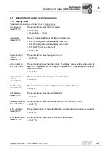
Power section
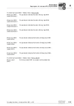
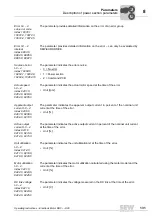
status t-0 – 4
index 8391.0,
8392.0, 8393.0,
8394.0, 8395.0
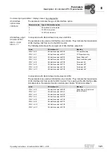
The parameter indicates the operating state of the power section at the time of the error:
• 0 = Inhibited
• 1 = Controller inhibit
• 2 = System error
• 3 = No enable
• 6 = Enabled
• 7 = Rapid stop
• 8 = Integrator stop
• 9 = Emergency stop
• 12 = Pos. operation
• 15 = Reference travel
Operating hours
t-0 – 4
index 8426.0,
8427.0, 8428.0,
8429.0, 8430.0
The parameter indicates the total number of hours for which the inverter has been
connected to the supply system at the time of the error.
• Storage cycle every 15 min
• Unit: [h]
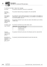
Enable hours
t-0 – 4
index 8431.0,
8432.0, 8433.0,
8434.0, 8435.0
The parameter indicates the total number of hours for which the power section was in
ENABLE operating state at the time of the error.
• Storage cycle every 15 min
• Unit: [h]
Work t-0 – 4
index 10083.1,
10083.2, 10083.3,
10083.4, 10083.5
The parameter indicates the total of active electrical energy the motor has consumed at
the time of the error.
• Storage cycle every 15 min
Heat sink
temperature
t-0 – 4
index 8396.0,
8397.0, 8398.0,
8399.0, 8400.0
The parameter indicates the heat sink temperature of the power section at the time of
the error.
• Unit: [°C]
Motor temperature
t-0 – 4
index 10070.1,
10070.2, 10070.3,
10070.4, 10070.5
The parameter indicates the motor temperature measured at the time of the error.
• Unit: [°C]
00
I


