Operating Instructions – Electronic Motor DRC.-..-DAC
135
8
Description of power section parameters
Parameters
8.4.3
Drive data
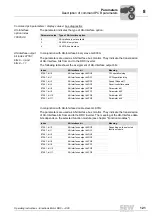
Power section parameters \ drive data \ motor parameters
Operating mode
index 8574.0
The parameter indicates the set operating mode:
• 16 = Servo
• 18 = Servo & IPOS
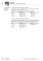
Direction of
rotation reversal
index 8537.0
The parameter indicate whether direction of rotation reversal was activated via DIP
switches.
• OFF: The motor turns CW for a positive setpoint and CCW for a negative setpoint.
• ON: The motor turns CCW for a positive setpoint and CW for a negative setpoint.
PWM frequency
index 8827.0
The parameter shows the nominal cycle frequency at the inverter output that is set via
DIP switches. The cycle frequency can change automatically depending on the unit
utilization:
• 0 = 4 kHz
• 1 = 8 kHz
Power section parameters \ drive data \ monitoring functions
The following monitoring functions have been implemented to monitor what happens to
drive-specific parameters in the specific application and to be able to react in case of
impermissible deviations. You can set the response to triggered monitoring functions
under "Unit functions/error monitoring".
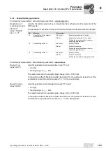
Speed monitoring
index 8557.0
This parameter is used to activate speed monitoring.
Setting range:
• OFF
• MOTOR MODE
• REGENERAT. MODE
• MOTOR / REGENERATIVE
The speed required by the setpoint can only be achieved if there is sufficient torque
available to meet the load requirements. Once the current limit (index 8518.0) has been
reached, the unit assumes that the torque has reached its maximum and the desired
speed cannot be reached. The speed monitoring function trips if this state persists for
the specified delay time (index 8558.0).
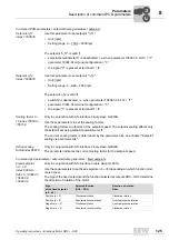
Delay time for
speed monitoring
index 8558.0
This parameter is used to set the delay time for speed monitoring:
• Setting range: 0 – 1 – 10 s
The set current limit can be reached briefly during acceleration, deceleration, or load
peaks. You can prevent the speed monitoring from responding too sensitively by setting
the delay time accordingly. The current limit must be reached permanently for the
duration of the delay time before the monitoring function trips.
00
I

