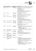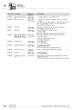
Operating Instructions – Electronic Motor DRC.-..-DAC
195
11
AS-Interface bus monitor
Service
11.7 AS-Interface bus monitor
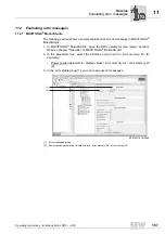
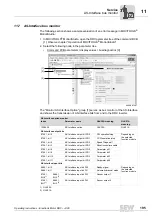
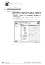
The following section shows a sample evaluation of an error message in MOVITOOLS
®
MotionStudio:
1. In MOVITOOLS
®
MotionStudio, open the DRC parameter tree of the command BCB
[1]. Observe chapter "Operation of MOVITOOLS
®
MotionStudio".
2. Select the following node in the parameter tree
• Command PCB parameters / display values / bus diagnostics [3]
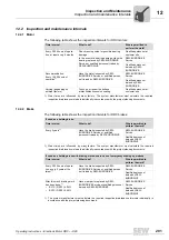
The "Monitor AS-Interface Option" group [1] serves as bus monitor of the AS-Interface
and shows the transmission of AS-Interface bits from and to the DRC inverter.
2452997387
AS-Interface option monitor
Index
Parameter name
GLK30A meaning
GLK31A
meaning
10095.39
AS-Interface option
GLK30A
GLK31A
AS-Interface output bits
9756.1, bit 0
AS-Interface output bit DO0
CW operation/stop
Depending on
the selected
function module
9756.1, bit 1
AS-Interface output bit DO1
CCW operation/stop
9756.1, bit 2
AS-Interface output bit DO2
Speed f2/speed f1
9756.1, bit 3
AS-Interface output bit DO3
Reset/controller enable
9756.1, bit 8
AS-Interface output bit PO0
Parameter bit 1
9756.1, bit 9
AS-Interface output bit PO1
Parameter bit 2
9756.1, bit 10
AS-Interface output bit PO2
Parameter bit 3
9756.1, bit 11
AS-Interface output bit PO3
Parameter bit 4
AS-Interface input bits
9866.1, bit 0
AS-Interface input bit DI0
Ready signal
Depending on
the selected
function module
9866.1, bit 1
AS-Interface input bit DI1
Automatic/manual mode
9756.1,
Bit 6
1)
1) GLK30A
9866.1,
Bit 2
2)
2) GLK31A
AS-Interface input bit DI2
Sensor output 1
9756.1,
Bit 7
9866.1,
Bit 3
AS-Interface input bit DI3
Sensor output 2
[3]
[2]
[1]

