Operating Instructions – Electronic Motor DRC.-..-DAC
47
5
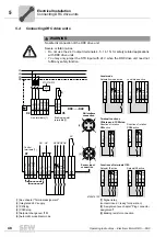
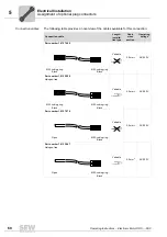
Terminal assignment
Electrical Installation
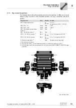
X7 control
terminals
1
STO +
Yellow
Input STO +
2
STO
−
Yellow
Input STO –
3
K1a
–
Signal relay
4
24V_O
–
DC 24 V output
5
0V24_O
–
0V24 reference potential output
11
STO +
Yellow
Output STO + (to loop through)
12
STO
−
Yellow
Output STO – (to loop through)
13
K1b
–
Signal relay
14
24V_O
–
DC 24 V output
15
0V24_O
–
0V24 reference potential output
21
n.c.
–
Not assigned
22
DI01
–
Binary input DI01
23
DI02
–
Binary input DI02
24
DI03
–
Binary input DI03
25
DI04
–
Binary input DI04
X1 communi-
cation
terminals
–
AS+
–
AS-Interface data cable +
–
AS
−
–
AS-Interface data cable –
–
DI2
–
DI2 sensor input
–
DI3
–
DI3 sensor input
–
VO24
–
DC 24 V voltage supply for sensors
–
VO24
–
DC 24 V voltage supply for sensors
–
VO
⬜
–
0V24 reference potential for sensors
–
VO
⬜
–
0V24 reference potential for sensors
Assignment
Terminal
No.
Name
Marking
Function (permitted tightening torque)


