72
Operating Instructions – Electronic Motor DRC.-..-DAC
6
Description of control elements
Startup
6.4
Description of control elements
6.4.1
Overview of control elements
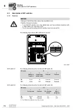
The following figure gives an overview of control elements on the DRC electronics cover:
9007201645995019
[1] DIP switches S1, S2
Switch t1
Switch f2
[2] Setpoint potentiometer f1 (underneath the gland)
[3] Diagnostic interface (underneath the gland)
[1]
[2]
[3]
O
N
DI
P
1
2
3
4
O
N
D
IP
1
2
3
4
3
5 6
4
3
5
6
4
6
5
f1
3
5
6
4
3
5
6
4
S1
S2
1 2
3 4
1 2
3 4
S1
S2
t1
f2
NET
RUN
DRIVE
00
I

