74
Operating Instructions – Electronic Motor DRC.-..-DAC
6
Description of DIP switches
Startup
6.5
Description of DIP switches
6.5.1
Overview
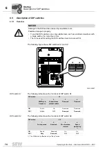
The following figure shows DIP switches S1 and S2:
DIP switch S1
The following table shows the functions of DIP switch S1:
DIP switch S2
The following table shows the functions of DIP switch S2:
NOTICE
Damage to the DIP switches caused by unsuitable tools.
Possible damage to property.
• To set the DIP switches, use only suitable tools, such as a slotted screwdriver with
a blade width of no more than 3 mm.
• The force used for setting the DIP switches must not exceed 5 N.
2391265547
34567
34567
ON
ADE04SA
1
2
3
4
ON
ADE04SA
1
2
3
4
t1
S1
S2
f2 f1
1 2 3 4
1 2 3 4
ON
DIP
1 2 3 4
ON
DIP
1 2 3 4
S2
S1
DIP switch
S1
1
2
3
4
PWM cycle
frequency
Brake release
without enable
Reserved
Reserved
ON
8 kHz
On
Reserved
Reserved
OFF
4 kHz
Off
Reserved
Reserved
DIP switch
S2
1
2
3
4
Startup mode
Reserved
Dir. of rotation
reversal
Speed
monitoring
1)
1) The DIP switch is effective only in "Easy" mode
ON
Expert
Reserved
On
On
OFF
Easy
Reserved
Off
Off
00
I

