Operating Instructions – Electronic Motor DRC.-..-DAC
81
6
Startup with binary slave GLK30A in "Expert mode"
Startup
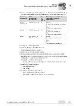
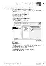
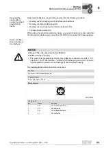
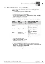
10.Check whether these parameters depend on mechanical controls and disable them,
if required, by adjusting the bit-coded selection box of parameter
index 10096.30
.
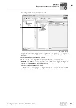
11.Change the selected parameters.
12.Check the functions of the DRC drive unit.
Optimize the parameters, if required.
13.Disconnect the PC from the DRC inverter.
14.Make sure the screw plug of the diagnostic interface has a seal and screw it in.
NOTICE
Loss of the ensured degree of protection if the screw plug of the diagnostic
interface is not installed or not installed correctly.
Damage to the DRC electronics cover.
• Make sure the screw plug of the diagnostic interface has a seal and screw it in.
15.Switch on the following voltages.
• AS-Interface voltage
• Line voltage
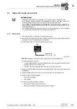
16.Set the required AS-Interface address.
• With a hand-held programming device
• With an AS-Interface master (see description of master)
Mechanical
control element
Affected
parameter index
(command pcb)
Bit
of
index
10096.30
Effect of parameter index 10096.30
(deactivation of mechanical
control elements)
Setpoint
potentiometer f1
10096.35 setpoint n_f1
13
Bit not set:
Setpoint f1 is set with setpoint potentiometer
f1
Bit set:
Setpoint f1 is set using parameters
Switch f2
10096.36 setpoint n_f2
14
Bit not set:
Setpoint f2 is set with switch f2
Bit set:
Setpoint f2 is set using parameters
Switch t1
8807.0 Ramp t11 up
8808.0 Ramp t11 down
15
Bit not set:
The ramps are set with switch t1
(acceleration ramp time = deceleration ramp
time)
Bit set:
The ramps are set using parameters
00
I

