118
Operating Instructions – Electronic Motor DRC.-..-DAC
8
Description of command PCB parameters
Parameters
8.3
Description of command PCB parameters
8.3.1
Display values
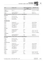
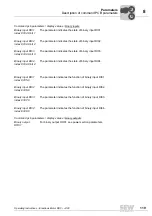
Command pcb parameters \ display values \ unit status
Operating status
index 8310.0
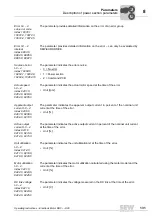
The parameter indicates the current operating state. The following operating states are
possible:
• READY
• NOT READY
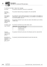
Startup mode
index 10095.1
This parameter shows the startup mode set with DIP switch S2/1 in plain text:
• EASY
• EXPERT
Setting of DIP
switch S1, S2
index 9621.10
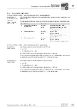
The parameter indicates the setting of DIP switches S1 and S2:
Display of the DIP switch setting is independent of whether the DIP switch function is
activated or deactivated.
Setting of switch f2
index 10096.27
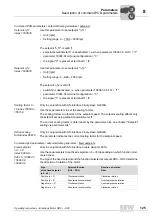
The parameter indicates the setting of switch f2.
Display of the switch setting is independent of whether the switch function is activated
or deactivated.
Parameter setting
of switch t1
index 10096.29
The parameter indicates the setting of switch t1.
Display of the switch setting is independent of whether the switch function is activated
or deactivated.
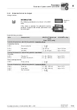
Command pcb parameters \ display values \ analog setpoints
Setting of setpoint
potentiometer f1
index 10096.28
The parameter indicates the setting of setpoint potentiometer f1.
The display of the switch setting is independent of whether the potentiometer function is
activated or deactivated.
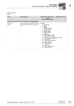
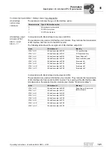
DIP
switch
Bit in index
9621.10
Functionality
S1/1
0
PWM cycle frequency
0: 4 kHz
1: variable (8, 4 kHz)
S1/2
1
Brake can be released without enable
0: Off
1: On
S1/3
2
res.
Reserved
S1/4
3
res.
Reserved
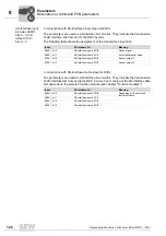
S2/1
4
Startup mode
0: Easy
1: Expert
S2/2
5
res.
Reserved
S2/3
6
Direction of rotation reversal
0: Off
1: On
S2/4
7
Speed monitoring
0: Off
1: On
00
I


