Operating Instructions – Electronic Motor DRC.-..-DAC
121
8
Description of command PCB parameters
Parameters
Command pcb parameters \ display values \ bus diagnostics
AS-Interface
option index
10095.39
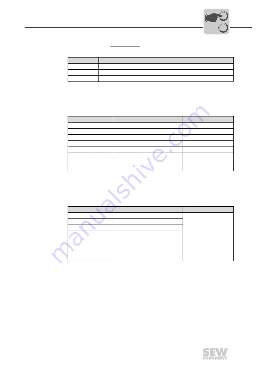
The parameter indicates the type of AS-Interface option:
ASInterface output
bit index 9756.1,
bits 0 – 3 and
bits 8 – 11
In conjunction with AS-Interface binary slave GLK30A:
The parameters are used as AS-Interface bus monitor. They indicate the transmission
of AS-Interface bits from and to the DRC inverter.
The following table shows the assignment of AS-Interface output bits:
In conjunction with AS-Interface double slave GLK31A:
The parameters are used as AS-Interface bus monitor. They indicate the transmission
of AS-Interface bits from and to the DRC inverter. The meaning of the AS-Interface data
bits depends on the selected function module (see chapter "Function modules").
Parameter value
Type of AS-Interface option
0
AS-Interface is not available
3
GLK30A binary slave
4
GLK31A double slave
Index
AS-Interface bit
Meaning
9756.1, bit 0
AS-Interface output bit DO0
CW operation/stop
9756.1, bit 1
AS-Interface output bit DO1
CCW operation/stop
9756.1, bit 2
AS-Interface output bit DO2
Speed f2/speed f1
9756.1, bit 3
AS-Interface output bit DO3
Reset/controller enable
9756.1, bit 8
AS-Interface output bit PO0
Parameter bit 1
9756.1, bit 9
AS-Interface output bit PO1
Parameter bit 2
9756.1, bit 10
AS-Interface output bit PO2
Parameter bit 3
9756.1, bit 11
AS-Interface output bit PO3
Parameter bit 4
Index
AS-Interface bit
Meaning
9756.1, bit 0
AS-Interface output bit DO0
Depending on the selected
function module
9756.1, bit 1
AS-Interface output bit DO1
9756.1, bit 2
AS-Interface output bit DO2
9756.1, bit 3
AS-Interface output bit DO3
9756.1, bit 8
AS-Interface output bit PO0
9756.1, bit 9
AS-Interface output bit PO1
9756.1, bit 10
AS-Interface output bit PO2
9756.1, bit 11
AS-Interface output bit PO3
00
I

