Operating Instructions – Electronic Motor DRC.-..-DAC
137
8
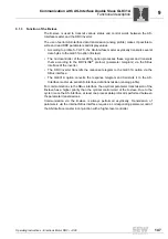
Description of power section parameters
Parameters
8.4.4
Terminal assignment
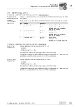
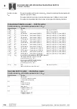
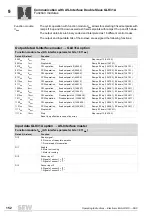
Power section parameters \ terminal assignment \ binary outputs
Binary output
DO01 (signal relay
K1) index 8349.0,
bit 1
The parameter indicates the status of binary output DO01.
Binary output
DO01 (signal relay
K1) index 8350.0
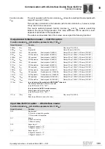
This parameter is used to specify the assignment of binary output DO01 (signal
relay K1). You can program the binary output to the following functions:
Function
Binary output has
"0" signal
"1" signal
0 = No function
Always "0" signal
–
1 = /Fault
Collective fault signal
–
2 = Ready
Not ready
Ready for operation
3 = Output stage ON
Unit inhibited
Unit enabled and motor
energized
4 = Rotating field ON
No rotating field
Rotating field
5 = Brake released
1)
1) Controlled by the inverter The "Brake released" and "Brake applied" signals are intended to be passed on
to a master controller.
In conjunction with mecha-
tronic MOVIGEAR
®
drive unit:
DynaStop
®
is activated
In conjunction with mecha-
tronic MOVIGEAR
®
drive unit:
DynaStop
®
is deactivated
In conjunction with DRC
electronic motor:
Brake applied
In conjunction with DRC
electronic motor:
Brake released
6 = Brake applied
In conjunction with mecha-
tronic MOVIGEAR
®
drive unit:
DynaStop
®
is deactivated
In conjunction with mecha-
tronic MOVIGEAR
®
drive unit:
DynaStop
®
is activated
In conjunction with DRC
electronic motor:
Brake released
In conjunction with DRC
electronic motor:
Brake applied
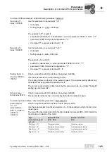
7 = Motor standstill
Motor is running
Motor is at standstill
8 = Reserved
–
–
9 = Speed reference signal
n > n
ref
(n < n
ref
)
n < n
ref
(n > n
ref
)
10 = Speed reference signal
Speed is outside (within) speed
window
Speed is within (outside) speed
window
11 = Setpoint/actual value
comparison signal
n <> n
set
(n = n
set
)
n = n
set
(n <> n
set
)
12 = Current reference signal
I > I
ref
(I < I
ref
)
I < I
ref
(I > I
ref
)
13 = Imax signal
I < I
max
(I = I
max
)
I = I
max
(I < I
max
)
14 = /Warning motor utilization 1
100% prewarning of motor
protection in parameter set 1
–
19 = IPOS in position
Position not reached
Position reached
20 = IPOS referenced
No referencing
Referencing finished
21 = IPOS output
Depends on IPOS program
22 = /IPOS fault
IPOS program error message
–
27 = STO – safe torque off
Not active
Active
34 = Process data bit
Bit not set
Bit set
00
I

