146
Operating Instructions – Electronic Motor DRC.-..-DAC
9
Functional description
Communication with AS-Interface Double Slave GLK31A
9
Communication with AS-Interface Double Slave GLK31A
9.1
Functional description
9.1.1
Operating principle
An AS-Interface master according to AS-Interface specification 3.0, rev. 2 in conjunction
with the M4 master profile is required for controlling the GLK31A double slave.
On delivery, the GLK31A option has address 0 and profile S-7.A.7.7. If you set an
address > 0, the GLK31A option turns into a double slave with profiles S-7.A.7.7 (A-
slave) and S-7.A.7.5 (B-slave).
You must not connect more than 31 of those slaves to one AS-Interface branch.
9.1.2
A-slave, meaning of the AS-Interface data and parameter bits
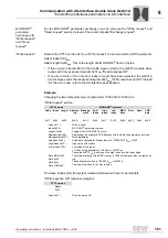
The AS-Interface master transmits data bits and parameter bits to the GLK31A option
(A-slave). The GLK31A option forwards 4 data bits and 3 parameter bits via SBus
communication to the DRC inverter without interpretation.
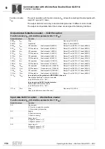
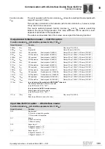
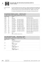
The DRC inverter contains several function modules (assignment tables) that assign
specific drive functions to the data bits. For information on the assignment of functions,
refer to chapter "Function modules".
Parameter bits
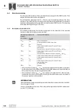
• 3 of the acyclic parameter bits (P2 – P0) are used for switching between the individ-
ual function modules. These parameter bits determine the meaning of the data bits.
• In the extended address mode, the fourth parameter bit is not available for the user.
• Parameter selection between the function modules is also possible during operation
and with enabled DRC inverter. The meaning of the data bits might change in this
case.
• The parameter input bits are not used.
Data bits
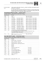
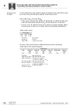
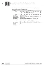
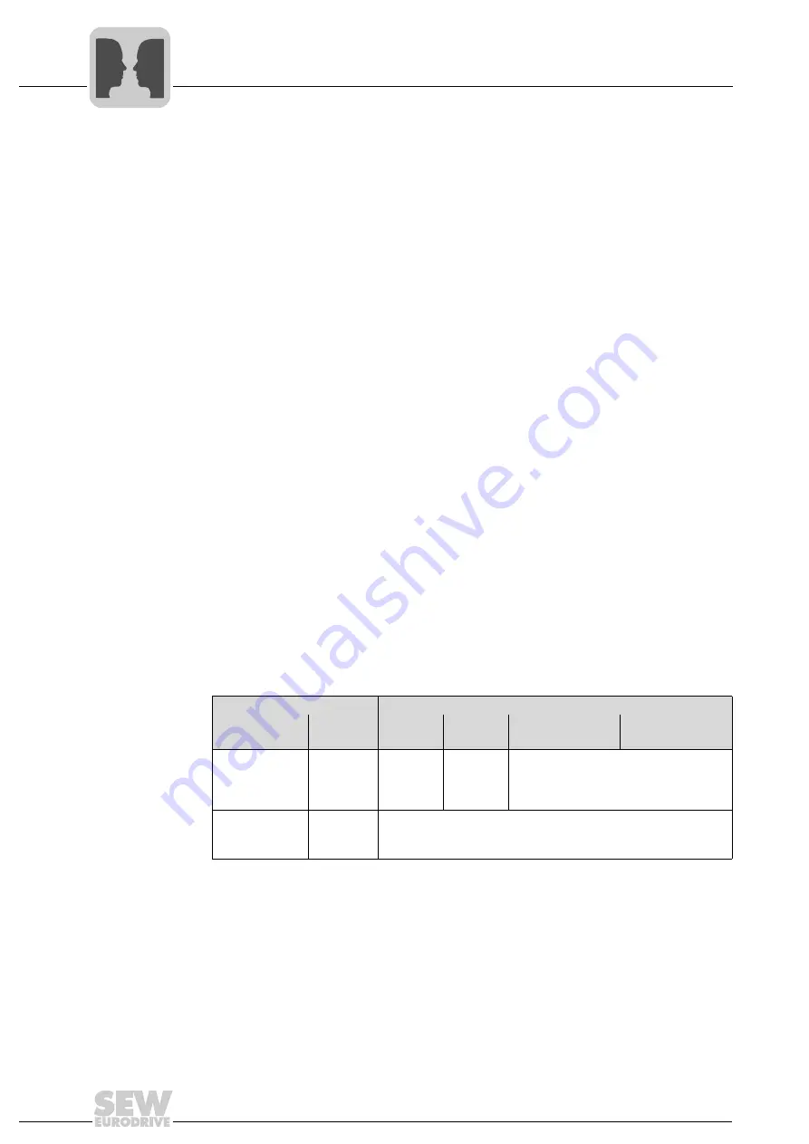
The following table show the assignment of the binary input data bits of the A-slave
(cycle time: max 10 ms):
Parameter bits P2 – P0 are used for selecting the function modules.
• When function modules 2
hex
– 7
hex
are selected, data bits DI0 and DI1 are transmit-
ted from the slave to the master according to the DRC status word. Data bits DI2 and
DI3 contain the state of sensor inputs DI2 and DI3.
• When function modules 0
hex
– 1
hex
are selected, all 4 data bits DI0 – DI3 are trans-
mitted from the slave to the master according to the DRC status word. The state of
the sensor inputs is not transmitted.
Parameter bits (A-slave)
Function of the input data bits (A-slave)
(P2 P1 P0
bin
)
Function
module
Bit 4
(DI3)
Bit 3
(DI2)
Bit 2
(DI1)
Bit 1
(DI0)
010
bin
– 111
bin
2
hex
– 7
hex
(2hex +
6hex =
reserved)
Status
Sensor 2
Status
Sensor 1
DRC status
according to
chapter "Description of data bits, function
modules"
000
bin
– 001
bin
0
hex
– 1
hex
(0hex =
reserved)
DRC status
according to
chapter "Description of data bits, function modules"


